Predicting the future for switches and crossings
Posted: 17 September 2010 | | No comments yet
Maintaining and renewing the thousands of switches and crossings (or ‘S&C’ and also known as railway points and/or turnouts) across Britain’s rail network is an expensive business, costing hundreds of millions of pounds every year. Gaining a better understanding of the dynamic forces that occur when a train passes over a set of points is key to improving their maintenance and reliability, helping to reduce operating costs and disruption.
Maintaining and renewing the thousands of switches and crossings (or ‘S&C’ and also known as railway points and/or turnouts) across Britain’s rail network is an expensive business, costing hundreds of millions of pounds every year. Gaining a better understanding of the dynamic forces that occur when a train passes over a set of points is key to improving their maintenance and reliability, helping to reduce operating costs and disruption.
Maintaining and renewing the thousands of switches and crossings (or ‘S&C’ and also known as railway points and/or turnouts) across Britain’s rail network is an expensive business, costing hundreds of millions of pounds every year. Gaining a better understanding of the dynamic forces that occur when a train passes over a set of points is key to improving their maintenance and reliability, helping to reduce operating costs and disruption.
We are undertaking a pioneering study at the Future Railway Research Centre (FRRC), within Imperial College London, to develop a better understanding of the dynamic wheel-rail loads occurring throughout switches and crossings.
After taking over from Railtrack in 2002, Network Rail has been committed to restoring Britain’s railway network to record levels of track quality and train punctuality. Maintaining this commitment, Network Rail recognised the importance of reintroducing research and development activities as the infrastructure owner. In 2008-2009, three strategic research centres were established, each with a core research stream. Imperial College London are commissioned to research ‘Towards the 2030 Railway’, the University of Sheffield are investigating ‘The Intelligent Railway’ and the University of Nottingham are focussing on ‘Infrastructure Asset Management’. Our research at Imperial College London is seeking to determine why some S&C units fail quicker than others.
By gaining an in-depth understanding of these dynamic forces, we are aiming to develop a computational tool capable of predicating realistic material degradation within S&C throughout their operational life cycle. This will enable engineers to improve the way S&C equipment is maintained and enable them to be renewed more efficiently.
S&C units are one of Network Rail’s most critical and complex infrastructure assets. Network Rail owns and maintains in excess of 21,000 S&C units within Britain’s mainline rail network. With an approximate total of 19,300 track miles, and an idealised switch and crossing length of 67.5m/unit, only approximately 5% of the mainline rail network is taken up by S&C.

Figure 1 Newly assembled S&C unit ready for installation
It may therefore be surprising that around 24% of all critical wrong side failures cited in the Hazard Directory – with scores of 50+ depending on line speed, tonnage, complexity, route environment and the line type – occur within S&C.
In 2009, Network Rail spent approximately 17% of its annual maintenance and a quarter of its renewal budget on S&C alone. Excluding unplanned, emergency maintenance and renewal activities, this commitment totalled more than £240 million.
Within the current five year investment programme, Control Period 4 (CP4), Network Rail plans to renew over 1,700 S&C units, equating to well in excess of £850 million by 2014. So, not only are S&C units extremely important and complex assets, maintaining and renewing them is an extremely expensive business.
Achieving predictive maintenance
A critical element of today’s state-of-the-art railway computational modelling is the wheelrail interface calculation. The phenomenon of wheel-rail contact is the driving force for rail vehicle dynamics and enables us to predict subsequent material degradation.
Commercially available rail vehicle dynamics software packages, such as VAMPIRE and SIMPACK, have and are still being used for detailed, accurate vehicle-track interaction studies. So why not use these for long-term S&C degradation predictions?
The answer lies within the key assumptions embedded within the wheel-rail contact theories. These theories are perfectly suitable for simple rail geometries, such as those associated with plain line, but complex, variable geometries, as found within S&C, present new difficulties.
One of our research streams focuses on this very problem. Methodologies for short-term material degradation predictions have already been proven. These techniques include the use of Multi-body Simulation (MBS) software packages to predict realistic vehicle dynamics through S&C.
Factors such as wheel-rail contact loads and contact positions are then retrieved and used to help create material degradation models. This step allows small changes in the material due to wear and plastic deformation to be modelled, and results in the creation of new rail profiles.
These profiles can then be updated within the simulation model and the process repeated in order to develop a time history of overall S&C degradation (see Figure 2).

Figure 2 S&C degradation modelling process
For this approach to be effective within switch and crossing studies, small errors associated with existing wheel-rail contact models must be eliminated. Over time, these small errors will accumulate to produce unacceptable inaccuracies, generating unreliable calculations as a result.
To overcome this, our research will investigate new wheel-rail contact theories that account for multi-point contact and that are not limited to elastic material behaviour and the elastic half-space assumption.
A brief history of wheel-rail contact and material degradation
Over the last two centuries, there have been a number of key contributors to the fields of contact mechanics and material degradation. These contributions have seen the expansion of theoretical and computational techniques now capable of predicting complex elastic contact behaviour at the wheel-rail interface. The most famous of all were the works of one Heinrich Hertz. Hertzian normal elastic rolling contact theories have been the backbone of almost all wheel-rail rolling contact solutions to date. Until the 20th century, very little work has been attempted to question the key assumptions that drive the theories of the past. Such assumptions include elastic material behaviour and compliance with the ‘half-space’ criteria (i.e. wheel-rail contact radii are significantly greater than the dimensions of the contact patch). The very nature of the wheel-rail contact through complex switch and crossing geometries begins to violate these very assumptions.
Rail vehicle dynamics simulation packages of today all use the theories of the past. For accurate S&C degradation predictions, new techniques must be developed and introduced that are not bound by outdated assumptions.

Figure 3Wheel-rail contact and material degradation timeline
Failure is not an option…
Switches and crossings are composed of a variety of key components, including switch rails, stock rails, crossings, wing rails, point operating equipment, point heaters, rail pads, bearers, switch rollers, and slide plates, to name but a few. At a higher level, the entire S&C unit can be split into three key zones: the switch panel, closure panel and crossing panel (see Figure 4).
Our research project will focus on deformation that occurs within both the switch and crossing panels.
Turnouts are identified by the switch length and the crossing angle at which the switch rail intersects the opposing stock rail at the crossing nose. Each switch is given a corresponding ‘switch length’ letter for identification, ranging from ‘A’ to ‘H’ (with an additional ‘SG’ being added between ‘F’ and ‘G’).
Each letter represents a restriction in speed and tonnage that the vehicles are allowed to enter the diverging route (with the through route relating to the line speed and tonnage of the location). These identifications give us a good comparison of the interaction with speed and delay minutes, as in theory the higher the speed, the greater the delay minutes.

Figure 4 Diagram of a typical railway turnout
All train delays on the railway are logged within a general database of train punctuality called TRUST (Train Running System TOPS [Total Operations Processing System], first introduced by BR in the mid 1980s). The train’s original planned journey details are compared to a parallel record, which states actual departure, arrival and passing times at designated locations in order to calculate delays against the published timetable. Each delay is referenced to a delay number, indicating designated incidents, and are categorised for performance analysis. This data is then logged against the Network Rail Fault Management System (FMS), which enables further analyses to be carried out.
Within this phase of the research project, a major task involves filtering the available data in an attempt to identify failure trends. This is no easy feat as, due to the massive amount of delay and incident data available, the analysis becomes difficult and extremely time consuming.
Once sufficient, high-quality data has been collected, the next challenge will be to progressively break down the data in an attempt to identify the causes associated with the most significant failure modes within a chosen reference turnout such as wear, plastic deformation and fatigue. This reference turnout will then become the base of the investigation and research.
Validation is the key
The introduction of computational models developed to predict future events, or indeed the collection and presentation of data trends, naturally brings a level of uncertainty or scepticism.
To reduce these feelings of doubt, a critical part of our research will be the validation of results. In order to validate trend and prediction results, real-time data must be collected. There are a number of ways of doing this, including the use of specialist equipment.
Accurate data for both computational model inputs and validation of outputs is essential to ensure accurate and realistic predictions are made. As with all modelling processes, poor data will produce unrealistic and unreliable results.

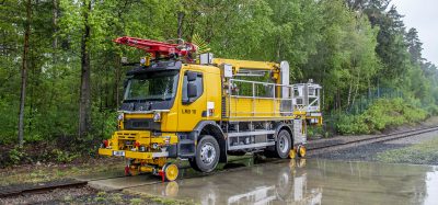
Figure 5 MiniProf (including a switch and crossing baseplate) collecting rail profiles from a switch blade in a manufacturer’s yard
For this project, a variety of validation techniques have been proposed. Those identified include the use of strain gauges, accelerometers (or potentiometers, we are currently undecided which will give us more useful information), a load measuring wheelset (sometimes called an instrumented wheelset) and MiniProf rail profiling equipment.
The MiniProf (see Figure 5) allows the user to collect real-time rail profiles through manoeuvring a wheel over the head of the rail. Outputs from a series of transducers are recorded at a maximum measurement rate of 100,000 points/s, and a file containing x-y rail profile co-ordinate data, to the accuracy level of a micron, is created.
This information can be used to import ‘real’ rail profiles into sophisticated rail vehicle dynamics modelling software (which include multi-body simulation packages). A simple example of MBS track forces generated as a vehicle negotiates a 400m curve containing a twisted closure rail is illustrated (see Figure 6).

Figure 6 Rail vehicle dynamics simulation using SIMPACK
Collecting rail profile data for inputs to rail vehicle simulations is not the only use for the MiniProf equipment. Another benefit includes being able to monitor the rail profile deformation at a specific location over time. Figure 7 shows a rail profile before (blue) and after (pink) grinding. This data has been imported to Microsoft Excel; however, with the software provided with the equipment, any change in the rail profile can be monitored and calculated directly.
The MiniProf rail profiler has been demonstrated as a key tool for generating MBS input data and validating the change and deformation in rail profiles. However, this is not the only area of validation. To build confidence in the computational model, simulated track forces must also be validated as this is the input data used for material degradation modelling.
Actual wheel-rail contact forces must also be monitored. The techniques available to achieve this include the use of strain gauges, accelerometers and a load measurement wheelset.
Each of these techniques has their own pros and cons. The load measuring wheelset is capable of providing high-frequency wheel-rail contact data (150Hz for lateral forces and up to 2000Hz for vertical) and can be installed on existing infrastructure monitoring vehicles, such as Network Rail’s New Measurement Train (NMT), so that complete coverage all main line S&C units becomes possible.
Example data available from the instrumented wheelset includes vertical wheel load contact forces (Q) measurements, lateral wheel-rail forces (Y) and longitudinal creepage forces (X).
All of this accurate and high-frequency data of course comes at a cost, which includes time needed to filter through all the data.
Strain gauges and accelerometers can also be used to measure the dynamic forces that occur as a vehicle passes over an S&C unit. This is a localised technique as the instrumentation is attached directly to the S&C unit. Data can be collected at a wide range of amplitudes and frequencies; however, the information obtained will only relate to the individual S&C unit being monitored.
Despite this, the advantage of being able to obtain load data from a known track geometry and quality for different vehicle types is invaluable as an exact replica can be modelled and validated. This then provides confidence when modelling S&C units where minimal validation data is available.

Figure 7 Rail profiles obtained from the MiniProf equipment
Concluding remarks
The aim of the PhD research is to provide Network Rail with a more accurate understanding of the dynamic forces that occur during the passage of rail vehicles through switches and crossings. In addition, a computational tool will be developed aimed at making accurate predictions of material degradation throughout the operational life cycle of switches and crossings. This will enable Network Rail to manage its network more cost effectively by optimising current maintenance and renewals practices. Completion of this PhD project will also provide a basis for further innovation and development.
About the Authors
Ian Coleman
In 2002, Ian Coleman attended the University of Leicester and graduated with a first class MEng (hons) degree in Mechanical Engineering. He then joined Network Rail on their Rail Vehicle Engineering graduate training scheme. Ian left the graduate scheme in 2007 to take up the role of Assistant Rail Vehicle Projects Design Engineer, where he spent the next 18 months developing his skills within design and structural analysis. His next move, within Network Rail, took his experience to the next level after gaining the role of Rail Vehicle Conformance Engineer in 2009. Within this role, Ian was responsible for overseeing design, calculation and build aspects of projects seeking engineering acceptance. His final move, towards the end of 2009, placed him into his current role as a PhD Student (Switches and Crossings) within the Network Rail S&C Systems Team in London. Ian now works full-time within the Future Railway Research Centre (FRRC) at Imperial College London on a PhD research project focussing on the optimisation of S&C maintenance and renewal regimes through predictive, computational techniques.
Andrew Cornish
Andrew Cornish graduated from the University of Birmingham in 2006 with a BEng (hons) in Mechanical Engineering. After completing his degree, Andrew went to take a year working for a small pre-fabricating plant room company before joining Network Rail in 2007 as a Graduate Engineer. With a grounding of the railways Andrew joined the FRRC at Imperial College London as a role within the newly formed switches and crossings team in Network Rail to complete research in early 2010, focusing on the experimental design and numerical analysis of the joint research project.