An introduction to validation challenges
Posted: 31 January 2017 | | No comments yet
Testing and validating an on-board ‘European Vital Computer’ (EVC) requires a specific test-environment with the ability to simulate all the stimulus, signalling and interfaces with which an EVC can exchange information. The European Union Agency for Railways has listed and publicly disseminated the performance requirements and guidelines to be utilised when developing such a facility. This article from Salvatore Vetruccio, Assessor – CCS On-Board Department at Italcertifer outlines the company’s efforts in developing such a system and the process that led to its success.

Our work began with the aim of designing a system of simulation that best reproduces the environment around EVC during the time a train is in operation: the proposed model has got to recreate (indoors) a full series of railway scenarios that the vital computer will face during its operational lifetime2.
The architecture of the test facility is a solution to the challenge
The test equipment called ‘ITCF_EuroSV’ was developed to manage and synchronise the following subsystems:
- A tool that translates the database, describing scenarios3 in a form usable by the subsequent subsystems
- A driving dynamics simulator tool
- An odometry system-simulator
- An RF communication system through air gap (ETCS Level 1)
- A simulator of bi-directional radio communication reproducing ETCS Level 2 signalling technology
- A system for digital commands and controls exchange with EVC
- Controlling software that oversees their behaviour and logs all the events.
Most components of this solution must accomplish real-time tasks, so the need to apply an embedded, deterministic logic unit is a key requirement.
Considering the total amount of computation expected, we opted for a chassis directly equipped with an FPGA core within, empowered by 45*106 gates (see Figure 1). This module is integrated on the same chassis with four electronic boards devoted to the following:
- TTL 5V analogical signals outputting (giving back the same square wave typical of sensors on revolving rail wheels)
- 24V I/O lines pilotage
- Serial ports management, with real time performances.
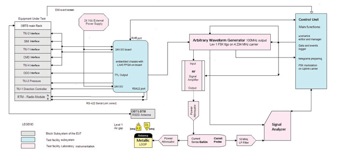
Figure 1: Block diagram that explains the connections between subsystems and the philosophy of
the data flow behind the testing process. Used acronyms are explained in Reference 1
Two general purpose PCs are still part of the project and they execute two main programmes: these procedures are not time critical, but are database managing, event logging, telegram encoding and message encrypting. The communication in Ethernet standard between the ‘Intel’ core of the PC and the deterministic FPGA is arranged by an intermediate layer, which is a necessary compromise between predictable execution scheduling and calculation power: a microprocessor based on RTOS, always keeping in mind that critical tasks are performed by FPGA completely independently.
List of functional entities, part of the test bench
The programme to simulate the driving dynamics
This is an interactive experience of simulated train driving in which a human user can control the traction effort and braking levels; and the software returns current position, speed, acceleration and pressure level in the main pipe. We have coded an analytical model of the train motion: all the main characterising features of a train are included (total mass, maximum traction, types of brake, pipe loading/unloading times, etc…).
Since it is possible to receive a fixed speed profile from the test session database, the software also includes an algorithm to autopilot the simulated run. The algorithm aims to respect a set of speed-check points or wait remaining standstill, permitting for instance interactions with Driver Machine Interface (DMI) of EUT.
Train board odometry system
Here TTL square waves are generated with a main frequency proportional to current train speed. The total amount of pulse detected determines the perceived distance from the start position. The system can reproduce four odometry devices: in fact, each of them returns two square waves with ±180° difference of phase, depending on the simulated train’s direction of motion.
Train status monitoring and conditioning system
EVC expects a series of digital input. Their states or their changes determine the flow of the test scenario. The status of some inputs is linked by the test database instructions to the current position, translated off-line by the adapting tool, while other statuses are dynamically determined by the simulated dynamics.
The pilotage of these switches is controlled by the FPGA logic in case of temporal drifts that would contaminate the sequence of events. The modules employed at the scope are two 24V I/O switch arrays. EVC can react by outputting other digital signals (such as emergency brake or traction cut-off) that are read by our system: these and all other incoming data from EVC are stored as compressed files into two different magnetic media. The analysis of these files is crucial in deciding the outcome of the test session.
Features of test sequences
As aforementioned, some features of the test sequences are still scanned and temporised by FPGA logic, but their off-line setting up can be realised by non-deterministic components. This is the case for signalling simulation realised by the RF instrumentation part of the test-bench4. These test sequence’s events occur when packets of FSK-modulated digital information need to be sent on a 4.234 MHz carrier.
A general purpose computer is entirely dedicated to the off-line preparation of the ‘telegrams’ (with large time constraints), to initialise and update RF instruments. It is loaded with a fairly high computational effort; in fact the programme converts the binary data received from the scenario descriptors into a large number of time samples containing the analogical FSK signal and the digital binary string modulated on it.
These ‘telegrams’, as well known, are orders, restrictions, or track information and are moved into the analogical domain by means of waveform generators, with the aim of reproducing in time domain the typical EM coupling between transmitting and receiving antenna (a metallic loop that mimics the ricetransmitting device of a generic ‘Eurobalise’ and the dual element part of the on-board under test system, respectively).
The parabolic trend is not casual: it is the result of data fusion between previously acquired samples. We sampled the power levels of the energising 27.095 MHz signal received from on-board downlink antenna, and also the threshold power level required by the uplink Eurobalise to activate itself.
This procedure has been repeated for various reciprocal positions between antennas into 3D space (with the help of an automated positioning tool, PLC controlled) and for various extreme conditions (e.g. antenna surrounded by water, ice, magnetite, etc. – see Figure 3).
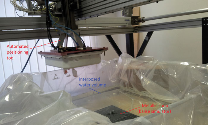
Figure 3: The preliminary phase of static data acquisition about EM coupling between antennas. The positioning arm is managed by a PLC which is piloted by dedicated software (written in order to be integrable with the rest of the environment) executed from one general purpose PC able to communicate with PLC through a serial RS232 link
These tasks are assigned to the dedicated PC and are computed before official tests begin.
The signal output from the Waveform Generator is finally amplified and sent to irradiate the receiving antenna – part of EUT.
The synchronisation strategy is aimed at preserving the determinism of the real-time system through a chain of analogical triggers that instantly disseminate the order to transmit.
A current probe is employed in order to sample the current flowing inside the loop, and its output is connected to a Vector signal analyser device devoted to checking the resulting power levels. The aforementioned sensor chain was also useful during the off-line preparation scenario: its power measures create a feedback to adjust the peak level of uplink power.
During the online phase, however, such a feature of the test bench is useful to dynamically recreate various coupling situations (e.g. compromised antenna with too weak, or too strong, an EM signal in uplink; maximum or minimum distance between antennas, interposed debris, etc…). The power peak levels are stored and then sequentially set for the sequence of Balise-Groups – part of the scenario track.
Real-time module
The real-time module is also charged with managing two I/O serial ports based on standard RS-422 with the aim of simulating two independent radio terminals. Two cable connections accomplish the bidirectional transference of communication primitives typical of ERTMS Level 2 signalling technology and disciplined by TSI5 .
These cable-ports are the links through which messages are exchanged between the different parts. Level 2 messages are fundamental to guarantee in the real world, as well as safety, performance and trackline-capacity. Data are directly injected to (or taken from) the EVC-radio-module, which is why no radio equipment is actually employed – there is no need to interact with the GSM-R network.
Nevertheless, respecting HDLC frame structure (the so-called layer 2) still remains mandatory, with its network protocol and transport layer overheads, as well as the ‘safety protocol’, set in order to respect functional mode ‘A1-type’ (reported in EN 501598 ).
In summary, it is requested to simulate the RBC behaviour, respecting all the prescriptions to preserve data integrity and robustness from external random corruption or voluntary tampering attacks. In order to accomplish these safety requirements, we enriched our system with the enciphering/deciphering process coding – the so-called DES modified MAC algorithm 36 – and by managing the ‘64bit-secret keys’. These are arrays of bits – always different in every communication session because they are negotiated between the parts during the initial authentication strings exchange.
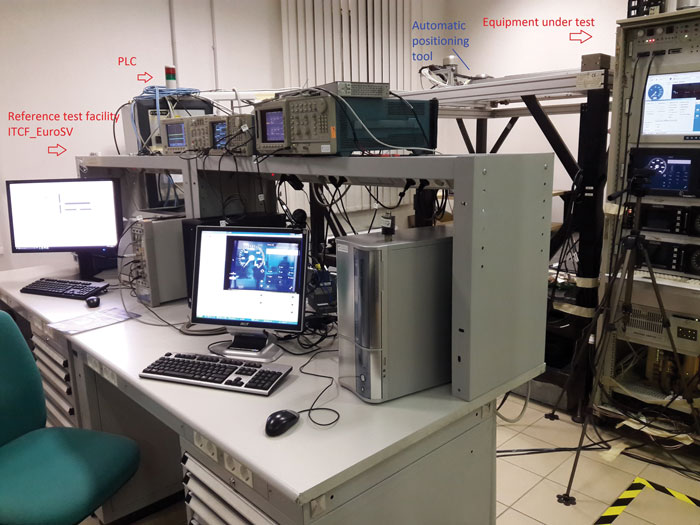
Figure 2: A complete viewing of ‘ITCF_EuroSV’ reference test facility
Conclusion
This test facility is now ready to check the functional behaviour of ERTMS/ETCS on-board equipment (see Figure 2). It has, in fact, positively concluded the evaluation process performed by a national accreditation institute. The test sequences provided by the European Union Agency for Railways2 are focused on compliance demonstration against requirements in Subset 0267 . In any case, our system is not limited to this. Instead our test-equipment donates the capability to recreate a personalised test scenario to the tester: we would go further and exploit the experience and creativity of the designed operator.
References
- Subset 094 – Functional Requirements for an on-board reference test facility
- Subset 076-6-3 – Test Sequences
- Subset 036 – Eurobalise FFFIS
- Subset 085 – Test specification for Eurobalise FFFIS
- Subset 037 v.3.0.0 – Euroradio FIS
- ISO/IEC 9797-1:2011 Information technology – Security techniques – Message Authentication Codes (MACs) – Part 1: Mechanisms using a block cipher
- Subset 026 – System requirements specification 8. CENELEC EN50129:2003
Biography
Salvatore Vetruccio is a M.o.E. in Optoelectronics Engineering. He has worked for Italcertifer S.p.A. (Gruppo Ferrovie dello Stato Italiane) since 2011 and is currently part of the Control-Command-Signalling assessor team and has spent recent years developing automated test benches and electronic mobile instrumentation devoted to assess subsystems in railway signalling. Salvatore now leads the Evaluation Technology Development Department within Italcertifer. He is also a Doctoral candidate at the University of Rome Tor Vergata where he is mainly involved with the development of automatic systems for simulation of high energy radiation physics and sources.