The journey of ballastless track
Posted: 23 August 2005 | | 1 comment
When the new high speed line Nüremberg-Ingolstadt is opened for service in 2006, more than 800km of ballastless track will be in operation in Germany. The different systems have undergone extensive laboratory and field tests before implementation on grade, bridges and in tunnels. Available measurement results indicate the expected favourable structural behaviour and prove the low maintenance requirements.
When the new high speed line Nüremberg-Ingolstadt is opened for service in 2006, more than 800km of ballastless track will be in operation in Germany. The different systems have undergone extensive laboratory and field tests before implementation on grade, bridges and in tunnels. Available measurement results indicate the expected favourable structural behaviour and prove the low maintenance requirements.
When the new high speed line Nüremberg-Ingolstadt is opened for service in 2006, more than 800km of ballastless track will be in operation in Germany. The different systems have undergone extensive laboratory and field tests before implementation on grade, bridges and in tunnels. Available measurement results indicate the expected favourable structural behaviour and prove the low maintenance requirements.
Advantages of ballastless track
With increasing speed and a lay-out of lines with extreme track parameters – e.g. to achieve a routing in parallel to existing motorways which has great advantages in respect of environmental aspects (e.g. less efforts for reduction of noise emission due to close neighbourhood) – the use of conventional ballasted track structure is limited. For example, the lay-out parameters of the 155km long ballastless track section of the Frankfurt-Cologne high speed line (Vmax = 300km/h) with a regular track radius of 3.350m, a cant of 170mm and a gradient of 40 per cent scarcely could have been realised with a conventional ballasted track structure according to the design standards of DB.
The infrastructure of the HSL Zuid in The Netherlands is built according to a so-called DBFM (Design, Build, Finance, Maintain) contract, and the availability has to be guaranteed at a specified high level of 99 per cent for 25 years1. Therefore, the awarded consortium, INFRASPEED, decided to perform a ballastless track in spite of the existing poor subgrade conditions.
For evaluation purposes, it is necessary to take into consideration the interaction between vehicle and track. Passengers have always assessed riding comfort in a train by their individual impressions. Old definitions from 1928 (Figure 1) could still be valid today when riding on the first and third generation of ICE along existing old ballasted tracks or on new high speed lines in Germany with ballastless track and trying to write in a notebook. However, there are still objective criteria to assess comfort, security and danger of distress of track components by measurement of forces and accelerations (Figure 2). Low axle loads (ICE 3 <170 kN compared with 198 kN for the ICE 1 and ICE 2) and low dynamic forces, which depend on unsprung mass and suspension systems as well as on maintenance intervals for reprofiling of wheel rims are required. The resistance against lateral track displacement (Prud’homme value SY) could be critical for a ballasted track with wooden sleepers due to its low dead weight, but not for a concrete slab track, especially when constructed continuously reinforced and herewith owing a very high moment of inertia in lateral direction.
The rail temperature also has to be taken into consideration as a security criterion in respect of the danger of track buckling. The ICE 3 uses linear eddy current brakes, which heat up the rails. An analysis by the equations in Figure 3 demonstrates that the critical temperature rise DTo for buckling of a conventional concrete sleeper track is exceeded if the extra heat from eddy current brakes sums up to 18 K. If eight trains per hour activate a braking force of 80 kN per rail at the same track section the addition temperature rise would be 25 K2, i.e. a conventional ballasted track would not be suitable. But for a slab track (S.T.) there is no risk of danger due to its rigidity.
Therefore, the main advantages of ballastless slab track can be concluded:
- Ensures excellent riding comfort at high speed
- The resistance against excessive forces is increased
- It enables the use of eddy current brakes
- No problems with ballast churning at high speed
- The average distance of crossovers, which are necessary for maintenance operations can be increased significantly (Frankfurt-Cologne line about 28km)
- No problems with vegetation control which is essential for a ballasted structure
- Reduction of structure height, especially in tunnels, (less aero-dynamic resistance, enables implementation of tilting trains in existing tunnels)
- The snaking railway route with extreme track parameters in hilly regions enables to save money due to less engineering of tunnels and bridges if a new line is constructed
- Assuming a matured slab track design and good quality a significant reduction of maintenance and a service life of 60 years is expected, which is the twofold value of conventional ballasted track
Development of concrete slab track
The development of ballastless slab tracks for full service railways was initiated in Europe in the middle of the 1960s by the planning of long tunnels where the track had to be laid directly on a rigid rock or concrete base. In Japan the same problem has arisen by the construction of the new Sanyo-Shinkansen lines, opened in 1973/74, where more than 80 per cent of the tracks had to be supported by rigid concrete structures; tunnels and viaducts are ideally suited for S.T.
In 1972 in Germany, an innovative structure was installed at Rheda station, consisting of a continuously reinforced concrete slab to which exactly aligned concrete sleepers were monolithically fixed by means of filling concrete (Figure 4). In spite of the excellent behaviour of this, about 700m long, ‘Rheda-structure’ on grade (no maintenance except rail grinding operations has been necessary up to date) further developments and applications of ballastless tracks have been at quite a low level until 1990. In 1991, new high speed lines (with a maximum speed of 250km/h with ICE and 120km/h with freight trains) in a length of 427km were opened to revenue service. Only about 15 track-km of ballastless track (Rheda type) and 5km of the ‘Züblin system’ were installed in four tunnels of these new high speed lines. While the S.T. sections demonstrated good behaviour, maintenance problems with ballasted track soon became evident, especially ballast wear.
The reason for the ballast deterioration is the high contact pressure of the ballast due to a rigid support especially on bridges but also on grade with the perfect compacted subgrade, frost blanket layer and granular protection layer. On the other hand, measurements of the vertical vibration velocity of the ballast demonstrated that the effective rms-values are doubled when the speed is increased from 160km/h to 250km/h. To counteract this phenomenon more resiliency has to be introduced in the ballasted track system. Figure 5 demonstrates the effect of high resilient fastening systems on the vertical vibration velocity3. However, this significantly increases the investment costs for a ballasted track.
Therefore, the board of DB AG decided in 1994 that, for all new high speed lines and upgraded lines to be constructed in Germany, the use of ballastless track has to be considered in the planning phase. This enables the railway to exploit the special advantages of the slab track structure in a much better way. This change of policy by the management of DB AG has spurred the road construction companies in Germany to develop new ballastless track structures4. Innovative structures have to be structurally designed and tested intensively in the laboratory before they undergo trials. In general, a distinction between three basic systems can be made.
Resilient fastening system
Due to the rigid structure of S.T., a dominant requirement for all systems is an elastic rail fastening. The deflection under a 20 tonnes axle load should be similar to that of a conventional ballasted track. Long-term experiences on the latter demonstrate that the load distributing effect of the rail can be optimised by a rail deflection of about 1.5 to 2.0mm. The standard fastening system 300 of DB AG for ballastless track ensures this deflection behaviour by a resilient base plate pad with a spring coefficient of 22.5 ± 2.5 [kN/mm]. The longitudinal creep resistance of the rail in one fastening system must exceed 7 kN to prevent excessive gap widening of the continuously welded rail in case of a rail fracture in winter.
Sleeper panel fixed by anchors to the pavement or embedded monolithically
The use of prefabricated sleepers guarantees exact gauge and rail inclination, which is essential for a stable wheel-set run and less wear at high speed. An advantage of systems with anchoring devices for the sleepers (Figure 6) is an easy reconstruction of sleepers in the case of derailment or deterioration. On the other hand, this design requires a precise paving of the concrete pavement (level tolerance ± 2mm) and a reduction in sleeper height tolerance (± 2mm) as only a 5mm thick geotextile at the bottom of the sleepers shall make up for contact irregularities.
In existing old tunnels a minimum structure height can be achieved by an asphalt pavement in a thickness of only 15cm, to which sleepers are fixed. The main feature of the GETRACA3-system are ‘wide sleepers’ fixed elastically by a concrete block on its underside, which is poured by a special mortar in a respective recess of the asphalt pavement. In the 3.04km long Brandleite-Tunnel the existing ballasted track was reconstructed in 2005 with this GETRAC-systems (Figure 7), which enables to increase speed by service with tilting trains due to the increased tunnel profile. Successful for the monolithical system has been the Rheda-family (Figure 8) and the Züblin-system. The difference is that with the Rheda system the concrete sleepers are laid on a continuously reinforced concrete slab and then embedded in stage II concrete, while with the Züblin system the concrete is first paved, after which the sleepers are vibrated exactly aligned into it. 38km of the new high speed line between Nuremberg and Ingolstadt are just under construction with the ‘Rheda 2000’-system, where lattice-type two block sleepers are used, ensuring a better bond between sleeper block and filling concrete at reduced construction height (Figure 9). The Rheda 2000 system is also used in The Netherlands on the HSL Zuid (Figure 10) which will be opened in 2006.
Discrete rail seats on a concrete slab
Essential for this structure is an accurately paved concrete slab. The acceptable tolerance of ± 2mm in height is much lower than in road construction. The construction of this structure can be highly mechanised, however it requires high technology and a specialised working team. All systems developed up to now demonstrated that the required accuracy cannot be achieved without any additional construction method, e.g. a special ‘finisher’ or final grinding of the concrete surface before fixing the resilient fastening system (Figure 11).
It is well known from highway construction that jointed concrete pavements with increasing slab length and decreasing thickness tend to curl under temperature and moisture differentials, and often demonstrate pumping phenomena at joints. Hence, for high speed service, the concrete slab should be installed continuously reinforced (steel content about 0.8 per cent of the concrete slab cross section) to ensure fine cracking with a spacing of about two metres and a crack opening of less than 0.5mm. From the results of different test sections, it is evident that the average crack spacing was reduced after three years from 3.3m to 1.6m, the maximum crack width remained constant with 0.3 to 0.4mm due to the additional development of cracks. The risk of loosening of dowels or anchor bolts of the fastening by free cracking can be minimised by transverse notches on top of the concrete slab with a spacing of 1.95m, which is after every third rail seat.
Pre-cast slabs or frames
For this type of S.T. structure on grade pre-cast 20cm thick concrete slabs, pre-tensioned in transverse direction, are laid on a cement-treated base course or asphalt pavement, adjusted by threaded spindles and afterwards undersealed with a liquid cement-asphalt-mortar (CAM) of low viscosity and high resistance against frost and erosion. The weakest part of this structure are the joints, which therefore should be coupled to reduce curling under temperature and moisture differentials and to prevent by shear transfer the critical loading case ‘free edge’, where the deflection increases to the 3.5-fold value of the loading case ‘slab interior’, which causes the danger of pumping phenomena.
At the test track ‘Karlsfeld’, constructed in 1977 (Figure 12), the protruding longitudinal bars were alumino-thermic welded after small parts of the joint had been filled up with cement mortar. Hence, the thermic shrinkage of the welds caused a certain prestressing effect in longitudinal direction. An excellent long-term behaviour was obtained to date. However, the investment costs have been very high.
This type of structure nowadays became interesting due to modern production methods of the slabs and a more simple kind of coupling the six longitudinal bars by sleeves. With the Bögl-system, the prefabricated slabs are 6.45m long and in transverse direction notched after each rail seat. Hence a fine cracking can be activated in a spacing of 0.65m, similar to the behaviour of a continuously reinforced concrete slab. Decisive for thickness design is the bending stress in transverse direction, which can be reduced by prestressing. After the construction of two test sections in 1999 (Rot-Malsch on cement treated base, Hattstedt on 30cm thick asphalt pavement) this system is under construction in a length of about 35km on the new Nüremberg-Ingolstadt high speed line (Figure 13).
A decisive prospect of slab track is that the investment costs are not too high in comparison with the standard ballasted track. When the less engineering structures (bridges and tunnels), the high speed (which requires efforts to increase resiliency of standard ballasted track) and significantly reduced maintenance are taken into consideration, the slab track is more superior to ballasted track. A reduction of investment costs deems possible by use of a frame-shaped slab track. In Germany, a test section was installed in 1988 (Hoesbach) where the short prestressed frames were undersealed by a hot mastix (‘Gussasphalt’, which requires no compaction) on an asphalt pavement (Figure 14), but its production costs were too high. Experiences in Japan, where this type was laid in a length of 130km in tunnels (Hokuriku Shinkansen line) demonstrated, that the costs for the frame-shaped track is eight to 14 per cent lower than that of ordinary slab track5. Consequently in Korea, a frame shaped S.T. was developed to be installed on the new high speed line under construction. By coupling the frames at the joints (Figure 15) and notching the surface of the frames, a similar long-term behaviour can be expected as with continuously reinforced concrete slabs or the coupled slab track system in Karlsfeld.
Special advantages of this type of structure are greater independency under unfavourable weather conditions and the possibility of opening to traffic soon after construction. Hence, for necessary reconstruction of a S.T., reduction of restraints can be expected.
Performance, deflection behaviour
Measurements by inspection cars on different concrete slab tracks demonstrate that the Q–values for track geometry remain nearly constant with increasing service time. Hence, for high speed traffic, a constant dynamic behaviour with increasing service time can be assumed, if a matured design and good quality is available.
In Figure 16, the mean static rail deflection of different S.T. at test section Waghäusel under a 200 kN-axle – as well as immediately after construction (1996) as after three years of revenue service (60 million gross tons) – are plotted. All structures demonstrate only small differences between both measurements. The required rail deflection of 1.5mm to 2.0mm is nearly met; it should be considered that the rail deflection is mainly influenced by the elastic behaviour of the resilient base plate pads of the fastening system. Considering unavoidable ageing effects and permanent deformations a spring coefficient of even under 20 kN/mm (ambient temperature) should be required. The somewhat higher rail deflection of system ‘F’ is influenced by a rail seat spacing of more than 0.65m. This wide rail seat spacing should not be used in high speed tracks due to the danger of periodic secondary deflections between the sleepers.
In Figure 17, the variation coefficient of static rail deflection for the same S.T. structures is plotted. The values give information about the scatter of resilient support. Experiences demonstrate that with a good aligned conventional ballasted track a variation coefficient of about 15 per cent is available shortly after tamping, however with increasing service time this value increases severely due to developing track irregularities. This value has been met with nearly all S.T. structures.
Dynamic deflection measurements (Figure 18) under high speed i.g. demonstrated no increase; the stiffening effect of the resilient pads and underground under dynamic loading has to be considered herewith. Hence for a S.T. of good quality at construction a constant dynamic behaviour can be assumed for high speed traffic. For the structuraldesign of S. T. a dynamic factor of 1.5 is sufficient, independent on speed6.
Conclusions
Ballastless concrete slab tracks of different design are in revenue service for more than thirty years. From the existing S.T. structures, an excellent long-term behaviour with a minimum of maintenance can be concluded, if a matured design is used and high quality is ensured at construction.


Figure 1: Definition of train riding quality from 1928
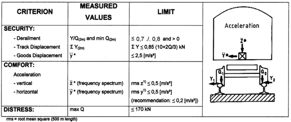

Figure 2: Criteria for vehicle-track-dynamic
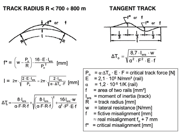

Figure 3: Theory of track buckling (Meier) - critical rail temperature raise to against neutral temperature
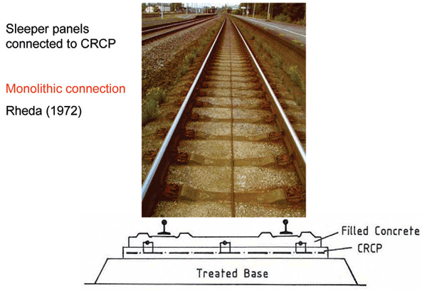

Figure 4: Classical Rheda section
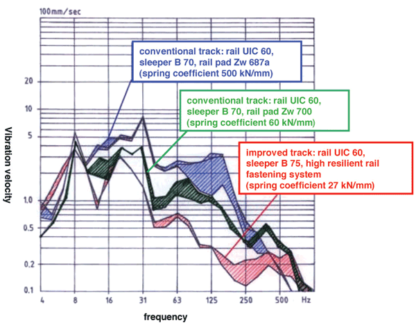

Figure 5: Vertical vibration velocity in ballast aggregates for structures with different resilient fastenings
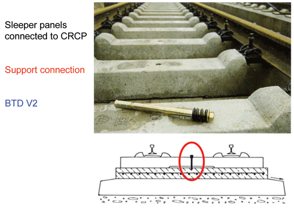

Figure 6: BTD V2-structurewith concrete sleeper panel and anchors on a continuously reinforced concrete slab
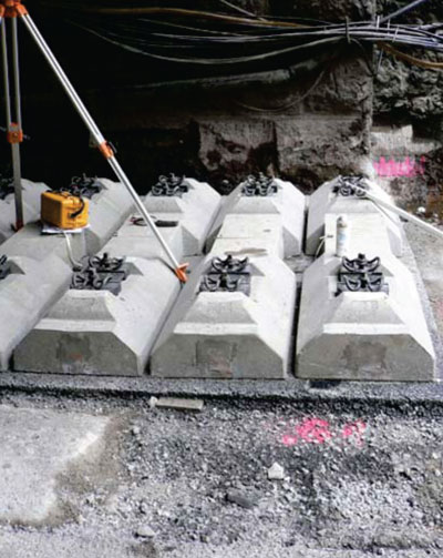

Figure 7: Wide sleepers on 15 cm wide asphalt pavement (GETRAC A3-system in Brandleite tunnel)
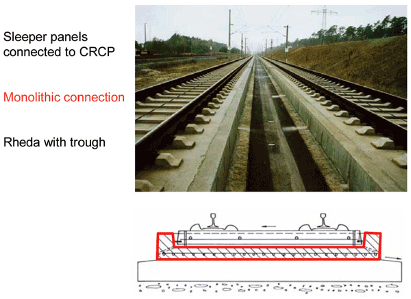

Figure 8: Rheda structure on the Hannover-Berlin line
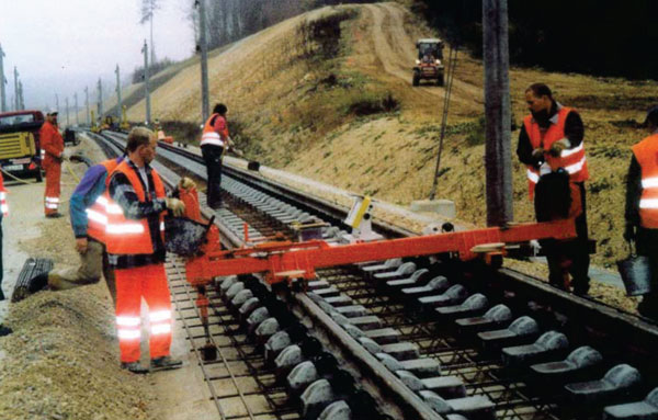

Figure 9: Rheda 200 system ( Pfleiderer) on the line Ingelstadt Nuremberg
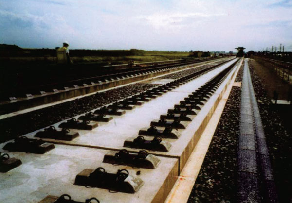

Figure 10: Rheda 2000 on settlement free plates at the HSL Zuid (The Netherlands)
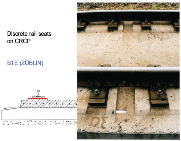

Figure 11: BTE slab track Of Zublin; discrete rail seats on a continuously reinforced slab with ground surface
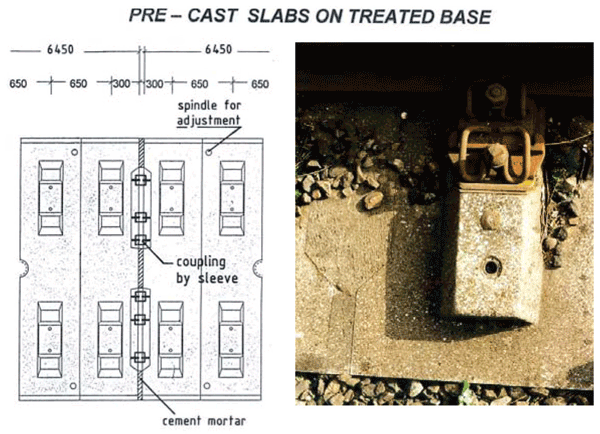

Figure 12: Test track Karlsfeld (1977) and Bogl system with coupling of continuous reinforcement
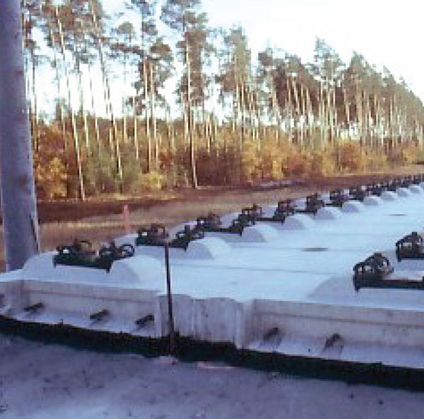

Figure 13: Bogl system on the line Ingolstadt-Nuremberg
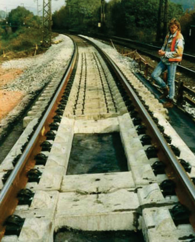

Figure 14: Test track Hoesbach (1988)
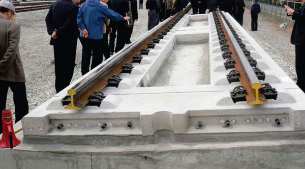

Figure 15: Frame shaped slab track development in Korea
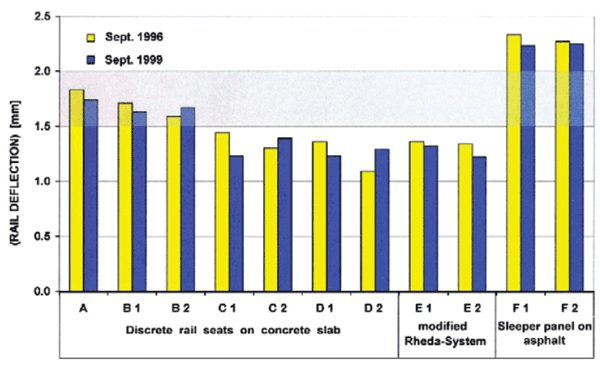

Figure 16: Mean static rail deflection (200 kN-axle)
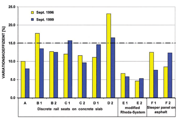

Figure 17: Variation coefficient of rail deflection
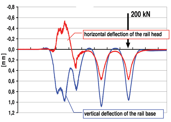

Figure 18: Measured rail deflections
References
- Esveld C.: Recent developments in slab track, Global Railway Review, Issue 2, 2003
- Jaensch E.: Slab track for high speed lines in Germany, Global Railway Review, Issue 4, 2003
- Leykauf, G., Stahl, W.: Concrete railway sleepers for the optimisation of ballasted track, Global Railway Review, Issue 2, 2004
- Leykauf G., Mattner L.: Ballastless track structures in Germany, Global Railway Review, Sept. 1995
- Ando K., Sunaga M., Aoki H., Haga O.: Development of Slab Tracks for Hokuriku Shinkansen Line, QR of RTRI, Vol. 42, No 1, Mar 2001
- Eisenmann, J., Leykauf, G.: Feste Fahrbahn für Schienenbahnen, Betonkalender 2000



I have proposed a concept that is based on installing solar panels along the length of a HS rail network so that the ballast-less tracks could be used as energy carriers. An example demonstrates that a 330 MW grid connected PV solar plant with battery storage for the Mumbai–Ahmedabad high speed rail link, generates electricity at $1.67× 10⁶ /MW output and levelized electricity cost at 12.05 c/kWh. Net saving in tariff after payback period is about $ 58 million per annum
Would request your kind comments on its feasibility.