New Dutch assessment of rail welding geometry
Posted: 2 March 2005 | | No comments yet
Delft University of Technology has developed new technical regulation standards for the geometrical deviations of metallurgic rail welds in The Netherlands, in cooperation with the Dutch rail infrastructure manager ProRail.
Delft University of Technology has developed new technical regulation standards for the geometrical deviations of metallurgic rail welds in The Netherlands, in cooperation with the Dutch rail infrastructure manager ProRail.
Like in all norms worldwide, the Dutch standards were based on establishing vertical (and horizontal) tolerances. In this way, only the maximum value of the longitudinal rail surface irregularity played a role, whereas the geometrical shape had no importance. However, this shape has a direct relation to dynamic wheel-rail contact forces, which may not be neglected, as these forces are at the source of many railway component defects and track deterioration mechanisms. Further, in the old standards the train velocity limitation for the line section in question had no influence.
In order to tackle this shortcoming, it was decided to develop a method to evaluate the overall dynamic quality of each individual realised weld-geometry, dependent of the line-section speed. This quality can be expressed in terms of dynamic effects occurring for train passage of the weld geometry. The concept is elaborated in the following article.
Theoretical backgrounds
Two different approaches are possible as a method for estimation of dynamic wheel-rail contact forces and their development in time: an approach linking vertical dynamic forces to the vertical acceleration of the un-sprung mass and another linking forces to its vertical velocity. Both methods are discussed in the following sections.
Acceleration approach
In a simplistic modelling it can be assumed that, when a train passes a weld in the rail, the un-sprung wheel-mass follows the vertical rail irregularity, which is considered as fixed. This assumption is correct from a dynamic point of view as long as the length-scale of the considered irregularity (or the time-scale of the excitation, both quantities are coupled by the train velocity) is large enough as compared to the period of vibration of the wheel-mass on the Hertz spring, or for a response which is quasi-static. In this simplistic approach the stiffness of the track and substructure is not taken into consideration. In a lumped modelling, this stiffness is frequency-dependent.
According to Newton’s second law the wheel-rail interaction force (denoted by Fdyn(t)) is equal to the inertia force originating from the wheel-mass M following the vertical irregularity z(x):


where z(t) follows from z(x) with x = vt, where v denotes the train velocity, given by the line-section speed in question.
A quasi-static response occurs for ω<ω0/2 approximately. The natural frequency of the wheel-mass on the linearised Hertzian spring is about1:


The excitation frequency equals, at a train velocity and a minimum wavelength L of 20mm:


The requirement for w now can be written as v<1.4m/s or v<5km/h. With train velocities up to 200km/h the requirement for the excitation frequency is obviously not satisfied. In combination with the variation in wavelengths in the signal this means the whole frequency-response domain is relevant and response may be far from quasi-static, especially for higher velocities. In addition non-linearities may play an important role.
However, to translate the complex dynamic contact-force problem into a geometrical problem, the approach according to (1) can be followed, as the curvature of the geometry is a measure for dynamic influences. In the dynamic problem, where the displacement of the wheel mass on the Hertz spring must be determined in order to calculate the spring or contact force, a differential equation (or more of them) must be solved, whereas in the geometrical problem only an algebraic equation must be solved to determine the contact force. A direct relation exists between the acceleration of the wheel-mass assuming that it follows the irregularity at a certain velocity, and the dynamic contact force. In terms of the vertical rail geometry, for (1) can be written:
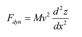

To get absolute values for the force in (2), a constant factor a should be added to account for dynamic influences and influence of the track stiffness. Its value can be chosen differently per line-section speed and should be determined from validation measurements.
Velocity approach
The vertical rail geometry in longitudinal direction is a function z(x) which can be transformed to the frequency domain (its discrete sampling via FFT).
When, analogously to (1), a contact force is assumed coupled to the second time derivative of the geometry, but with an equivalent mass linearly decreasing with the frequency or linearly increasing with the wavelength, can be written:


where me = M · λ/λ0, with λ0 some reference-wavelength. Starting from a harmonic signal z = z0 sin(2pvt / l), after some elaboration follows:
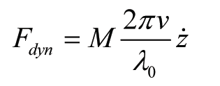

Due to the assumption of a linear relation between wavelength and effective mass, this expression is independent of l and holds for any arbitrary function z. Via dx = v·dt follows, in terms of the rail geometry (slope):
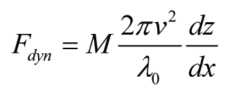

For qualitative comparisons, the reference-wavelength l0 can be taken as 2m, as the weld is measured with a 1m straightedge; the longest wavelength in the signal then results into me = M. To get absolute values from (3) a constant factor b may be added. Its value again may be chosen different per line-section velocity and should be determined from measurements.
Comparison
In both approaches the dynamic contact force problem was translated into a purely geometrical problem. This is important, as an evaluation of each individual weld geometry asks for a simple procedure to estimate occurring dynamic effects. A geometrical approach is easy to implement in a numerical code for the small processor of a measuring device, and what is most important: it is much faster than a dynamic approach. Further, both approaches allow a qualitative comparison between different rail geometries. To obtain quantitative results, the factors a and b should be validated via measurements.
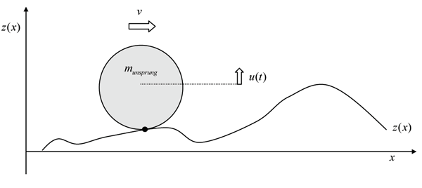

Figure 1: Wheel mass on irregular wheel
Derivation of welding standards
The intervention levels for the force, according to (2) and (3) respectively, have been derived in both cases by evaluation of a large sample of weld geometries, and are different per line-section speed. The measuring devices in use in The Netherlands sample the vertical rail geometry each 5mm. Before determining the derivatives of the discrete signal, it is averaged over a distance of 25mm (five data points), and a data point every 25mm is used (Figure 2). This is done to avoid very grassy signals for both derivatives due to very short-length micro-irregularities, which in reality will deform plastifically after a certain number of train passages.


Figure 2: Example of the measured and averaged weld geometry
In Figure 3 an example is shown of an averaged measurement signal of a weld geometry with both its first and second derivatives. All quantities have been scaled with their respective maxima. It is obvious that both derivatives provide a good estimation of the ‘smoothness’ of the longitudinal weld geometry. Both discussed approaches will be evaluated separately in the following.
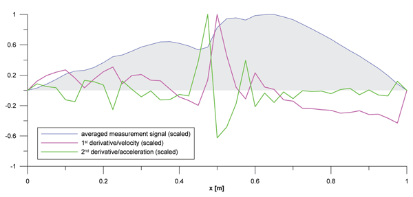

Figure 3: Dimensionless weld geometry, first and second derivatives (each quantity scaled with its maximum)
Acceleration approach
Evaluation of a large number of weld measurements from practice, according to expression (2), where the wheel-mass (half the un-sprung mass) is taken as 2000kg (and), leads to the following intervention levels in terms of the maximum force, per train velocity range:
- v ≤ 40km/h: 50kN
- 40 < v ≤ 80km/h: 100kN
- 80 < v ≤ 140km/h: 250kN
- 140 < v ≤ 200km/h: 500kN
The level of acceptation per velocity range has been determined subjectively, on the basis of experience. One would expect the same admissible force level for all velocity ranges, however, due to the quadratic velocity influence in (2), this turns out to be unfeasible. For example, the force corresponding to the maximum accuracy obtainable in welding for high speed lines would lead to tolerances in the order of centimetres for railway yards, which is unacceptable.
For the used sample of weld geometries (72), the percentage of rejected welds according to the old standards was 76%. According to the new system 33%, 64%, 93% and 94% are rejected respectively for the four velocity ranges.
Velocity approach
Following the same procedure as described in the previous section, but now applying expression (3) (with b = 1), leads to the following intervention levels for the force:
- v ≤ 40km/h: 2.5kN
- 40 < v ≤ 80km/h: 7.5kN
- 80 < v ≤ 140km/h: 17.5kN
- 140 < v ≤ 200km/h: 32.5kN
As both methods are not comparable, the same factor between the different force values (which, as discussed before, have only relative meaning) does not exist in both approaches. For the used sample of weld geometries, the percentage of rejected welds according to the new system is 33%, 53%, 81% and 86% respectively for the four velocity ranges.
Evaluation of both methods and choice for standardisation
To enable a comparison between both methods, a so-called quality index per weld is introduced. The calculated maximum force per weld is divided by the intervention level for certain velocity range. This way a dimensionless number is obtained; a quality index smaller or equal to 1 means acceptance of the weld. Comparison between both approaches shows that in general the velocity approach leads to less extreme values than the acceleration approach. This conclusion can also be drawn from the average scores for the analysed weld population. According to the acceleration approach, average quality indices were 1.2, 1.8, 3 and 3 for the four considered velocity ranges, and 1.2, 1.6, 2 and 2.2 according to the velocity approach, which is much more moderate.
In addition, the acceleration method turns out to be very sensitive for very small and short length irregularities (with length-scale centimetres) and not very sensitive for longer irregularities (with length-scale say 0.5m), which is not the case for the velocity approach. Very small, short length irregularities (indentations) often occur in welding of rails at both sides of the weld material, due to shrinkage after cooling down. In Figure 4 two examples are given of almost perfectly straight welds, but both with these indentations. The weld in Figure 4a has quality indices 1.3, 1.7, 3.3 and 3.3 according to the acceleration approach and indices 0.5, 0.7, 0.9 and 1 according to the velocity approach. For the weld in Figure 4b this is 1.3, 1.7, 3.3, 3.3 and 0.6, 0.8, 1, 1.1 respectively.
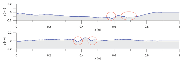

Figures 4a and 4b: Measurement examples of welds with indentations due to shrinkage due to welding
In Figure 5, an example is shown of a weld geometry with irregularity with a longer length-scale (the weld is of bad quality, with maximum height 0.8mm). The weld has quality indices 0.6, 0.9, 1.4 and 1.4 according to the acceleration approach and 1.1, 1.4, 2 and 2 according to the velocity approach.
On the basis of the above comparisons and the comprehensive analyses described in a report by TU Delft1 it was decided to adopt the velocity – or 1st derivative approach as the standard for vertical weld geometry assessment.


Figure 5: Measurement of a weld with irregularity with longer length scale
In Figure 6, a clear example is shown of the difference between the old and newly developed standards. The weld geometry, which shows an aggressive step, is accepted according to the old standards (before grinding, tolerance +0.3mm). However, according to the new standards the weld has indices 1.1, 1.7, 2 and 2.5 for the four velocity ranges and is rejected.


Figure 6: Measurement of a weld with a step
In Figure 7, an example is shown of an almost perfect weld. However, as it has some negative height coordinates, it is rejected according to the old standards. According to the new standards, the weld has indices 0.5, 0.7, 0.9 and 1 and is accepted for all velocity ranges.


Figure 7: Measurement of a weld with negative height co-ordinates
Via expression (3), the intervention levels for the force can be expressed directly in terms of the first spatial derivative of the vertical rail geometry (in milliradians):
- v ≤ 40km/h: 3.2mrad
- 40 < v ≤ 80km/h: 2.4mrad
- 80 < v ≤ 140km/h: 1.8mrad
- 140 < v ≤ 200km/h: 0.9mrad
- 200 < v ≤ 300km/h (high speed lines): 0.9mrad
where the last level has been determined assuming the same force level as for the velocity range 140 < v ≤ 200. A maximum slope of 0.7mrad is very close to the maximum accuracy obtainable in welding and grinding. The above given values for the spatial first derivative of the vertical rail geometry are the final standards for the vertical weld geometry adopted by ProRail.
For the horizontal weld geometry an empirical approach based on common practice was followed. In the lateral direction dynamics do not play an important role; the wheel-flange has only a real elastic contact with the railhead in curves, where in addition the rotating wheel-flanges grind off small imperfections. The following practical values were adopted:
- v ≤ 40km/h: +/– 1mm
- 40 < v ≤ 80km/h: +/– 0.7mm
- 80 < v ≤ 300km/h: +/– 0.5mm
Practical implementation
In practice, the new assessment of a weld (in vertical direction) is made according to the following steps (compare e.g. the RAILPROF measuring device2):
- The weld is measured with a 1m digital straightedge. The sampling interval of the vertical rail geometry equals 5mm.
- The software of the straightedge filters out irregularities with length-scale smaller than 25mm, calculates the first derivative of the geometry, and divides the discrete values of the first derivative by the speed dependent norm given earlier, after which the maximum is determined. In this way the dimensionless quality index (QI) of the weld is obtained.
- The geometry itself is scaled with a value of 1mm (as maximum) and is plotted together with the absolute value of the normalised first derivative on the graphical display so that the welding crew can immediately see the result of their work. If the above quality index is larger than 1 the weld is rejected and if smaller than 1 accepted.
In Figure 8 an example is given of the graphical output of a measuring device.
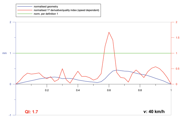

Figure 8: Screen output of a measuring device for the assessment of rail welds
Juridical framework
Motivation of renewal of regulations of ProRail3, 4 was to develop a clear and coherent standardisation, in order to avoid misunderstandings and miscommunication between European regulations and Dutch national standards, which were described separately in different assessment documents.
The new standardisation is based on the European norm EN 729-25, where general quality systems for welding are specified. According to this norm, the quality standard for welding companies that are allowed to produce rail welds for ProRail is defined. Different test certificates have been developed for assessment of the complete welding procedure, including the welding companies themselves, welding crew, welding materials and welding processes6. These certificates should be qualified by ProRail in order to obtain validity7.
After welding, each separate weld must be measured digitally and judged according to the new standards by the welding company before final acceptance by ProRail8. In addition, audits are carried out by ProRail. Further, a penalty system enables the exclusion of welding companies and crew delivering bad quality.
This entire qualification framework provides an efficient way to assure the observance of the new welding geometry standards.
Future developments
The framework as described in the previous section was developed by ProRail in cooperation with the most important Dutch welding companies. Evaluation of the new technical norms showed that they were usable and acceptable. The applied joint problem approach is unique and will be extended in the future; twice a year a session will take place with both ProRail and the welding companies to evaluate the results, implement feedback from practice and improve where necessary.
In the new assessment of welding geometry, the primary parameter is the dynamic wheel-rail force, whereas in the former situation this was the maximum height difference in the vertical geometry. It is clear that the dynamic force has a much more direct relation with damage to track and vehicle components. In addition, a differentiation on line-section velocity is introduced. However, some questions remain open. To answer these questions, in the near future research work will be carried out by ProRail and Delft University of Technology, where ProRail will provide real track measurement results to be used for verification and validation of theoretical models. In this future research, the following topics will be paid attention to:
- The level of acceptance, which was chosen more or less subjectively on the basis of experience, should be coupled to life cycle analyses, where the most critical component(s) in a track system should be determined. In this way an optimisation of the intervention levels can take place.
- Measurements should be carried out to both verify and validate expression (3), the basic tool for new welds assessment (and possibly also expression (1)), with respect to the coefficient for obtaining quantitative results.
- Monitoring of the initially realised weld geometry as a function of the passed tonnage (improvement versus deterioration of the weld quality as a result of plastic deformations and wear).
- Monitoring of the overall track quality (other track components) versus the initial weld quality and as a function of passed tonnage.
References
- M. J. M. M. Steenbergen, C. Esveld. Voorstel voor normering van lassen in spoorstaven. Report 7-04-220-7, ISSN 0169-9288, TU Delft, Delft, 2004.
- http://www.esveld.com
- RLN 00127-1. Operationele eisen voor metallurgische lassen in bovenbouwconstructies. Prorail, Utrecht, 2004.
- RLN 00127-2. Kadereisen voor metallurgische lassen in bovenbouwconstructies. Prorail, Utrecht, 2004.
- NEN-EN 729-2. Quality systems for welding – Fusion welding of metallic materials – Part 2: Comprehensive quality requirements. NEN, 1994.
- G.W. van Bezooijen. Private communications. Volker Stevin Rail & Traffic, Vianen, 2004.
- BEA 00206. Lastoevoegmaterialen en lasprocessen. Prorail, Utrecht, 2004.
- ACP 00127. Metallurgische lassen in bovenbouwconstructies. Prorail, Utrecht, 2004.


