Simulations of running dynamics in bogie design and development
Posted: 28 May 2008 | | No comments yet
Bombardier Transportation develops and produces bogies for a complete range of modern railway vehicles. The calculations and analyses of running dynamics play an indispensable part in the development of these products. This article outlines the usage of computer techniques to investigate vehicle dynamics during the individual product development phases of a project, the typical calculations and the latest challenges on running dynamics, illustrated with examples picked up among Bombardier’s experiences.
Bombardier Transportation develops and produces bogies for a complete range of modern railway vehicles. The calculations and analyses of running dynamics play an indispensable part in the development of these products. This article outlines the usage of computer techniques to investigate vehicle dynamics during the individual product development phases of a project, the typical calculations and the latest challenges on running dynamics, illustrated with examples picked up among Bombardier’s experiences.
Bombardier Transportation develops and produces bogies for a complete range of modern railway vehicles1, 2. The calculations and analyses of running dynamics play an indispensable part in the development of these products. This article outlines the usage of computer techniques to investigate vehicle dynamics during the individual product development phases of a project, the typical calculations and the latest challenges on running dynamics, illustrated with examples picked up among Bombardier’s experiences.
Running dynamics and engineering process
The phases of the railway vehicle engineering process in relation to time and knowledge of input parameters used for simulations of running dynamics are illustrated in Figure 1.
Dynamic simulations are already applied at an early stage for concept investigation and feasibility study. The models applied here are normally based on other similar vehicles and most of the input parameters are estimated. Input parameter uncertainty is covered by parameter variation and sensitivity tests.
The main part of the dynamic calculations takes place during vehicle design. In the optimisation (preliminary) design phase, the vehicle layout is specified, but the input parameters are based on a first estimation only. The parameters of suspension and other coupling elements have to be optimised based on the target values given by the standards and vehicle specification. Output values required for other engineering activities such as movements and loads are calculated to support the engineering process.
In the verification (detail) design phase, the vehicle topology is frozen. The vehicle is modelled in detail in order to acquire exact vehicle behaviour. The parameters of elements are specified and if possible also verified by measurements on prototype elements. The aim of the verification phase is to prove conformity with the limiting values stated in the standards and regulations, as well as the vehicle specification. A failure analysis and a sensitivity analysis can be provided as part of the verification calculations.
Later on, the vehicle acceptance and qualification tests are supported by vehicle dynamics calculations. During the test, the predicted and measured vehicle performance can be compared and the modelling improved to gain experience for future projects.
Although the engineering process has been completed when the vehicle is introduced into service, issues may subsequently, in rare situations, arise which then may require assessment using further vehicle dynamics simulations.
The engineering process of railway vehicle development in Bombardier Transportation is specified in the Bombardier Engineering Systems (BES). The analyses, deliverables and responsibility for vehicle dynamics are regulated within the BES process Design for Vehicle Dynamics.
Typical tasks and challenges
Modern and efficient programmes for the simulation of the multi-body systems with a wheel-rail contact element enable non-linear simulations for almost all running situations. The models built for the purpose of running dynamics calculations range from single vehicles up to complete train compositions. They possess dozens of rigid bodies and often several hundred degrees of freedom. The flexible structures of the carbodies or other sub-assemblies can be taken into account if required.
Vehicle dynamics calculations undertaken during railway vehicle engineering address the following areas:
- Fulfilment of customer specification
- Risk assessment
- Forecast and support of vehicle acceptance tests
- Support of other specialists during the design process
Typical dynamics analyses related to the mentioned tasks together with the aim and suitable methods are listed in Figure 2.
Eigenbehaviour and stationary tests
The assessment of the eigenbehaviour is one of the first calculations to be done following the model building. This investigation is carried out primarily for in-house requirements – it serves as a plausibility check and the first parameter optimisation. Quasi-static calculations of carbody roll coefficient and safety against derailment in twisted track constitute one of the trade-offs of bogie development. The roll coefficient limit is prescribed in continental vehicle specifications and must be complied with in relation to the vehicle gauging and the pantograph lateral movements. This requirement then limits the minimum vertical stiffness levels for the primary and secondary suspensions as well as the anti-roll device characteristics. In contrast, the requirements of safety against derailment on twisted track necessitate rather low stiffness. This trade-off becomes more critical in vehicles with deflated air suspension and constitutes one of the major challenges during bogie engineering. In order to avoid complex design of the (rarely used) emergency suspension, it is imperative that the margin of the safety against derailment is exploited in the case of vehicles with deflated air suspension running on twisted track.
The conditions for the testing of the safety against derailment are certainly defined within the scope of the stationary tests in the European standard EN 143633 concerning the testing for the acceptance of running characteristics of railway vehicles. However, some scope for application and interpretation is still open. For instance, purely the range between the minimum and maximum wheel/rail friction coefficient levels which must be maintained during the test influences the result decisively and can determine whether a particular vehicle will be approved or not. Our specialists in dynamics analyse the individual methods and influencing parameters, as well as support activities of UNIFE directed towards improving the assessment of safety against derailment.
Running stability
A further safety relevant criterion concerns stability. In the case of rail vehicles possessing conventional wheelsets, starting from a specific speed, self-excited oscillations called instability can arise. These vibrations not only lead to a deterioration of running characteristics, the emergence of high lateral forces between wheelset and track can also cause lateral track shift and thus precipitate derailment. The decisive influencing parameters are, apart from the vehicle parameters, the contact geometry between wheel and rail or more precisely wheelset and track and the wheel/rail friction coefficient. The equivalent conicity is applied as a simplified parameter in order to describe the wheel/rail contact geometry. The equivalent conicity can vary to a large degree and plays a significant role in the running behaviour of the vehicle. Whereas a very low conicity in modern vehicles sometimes leads to a deterioration of running behaviour in lateral direction as well as ride comfort degradation (see Figure 3) without exceeding the safety criteria, the high conicity limits the maximum permissible speed with respect to running safety. The range of equivalent conicities to be complied with during the vehicle acceptance tests is certainly defined in the European standard EN 143633. However, the individual track maintenance specifications often do not reflect these conditions with the consequence that the real conditions often widely diverge from the conditions defined in EN 14363. On the one hand, more and more alternative rail profiles are applied during rail grinding, leading to a lower conicity. On the other hand, very high conicity is often referenced in the vehicle specification, in order to cover all present track conditions occasionally containing track sections that are narrow-to-gauge or contain heavily worn rails.
These contradictory tendencies increasingly extend the range of the equivalent conicities with which the vehicle has to comply with. In addition to this, even the specification of an equivalent conicity is insufficient to provide the exact wheel/rail contact conditions necessary for stability assessment. Namely, the same equivalent conicity value can represent various contact geometries and, according to the chosen method of analysis, each can lead to differing critical speeds as can be seen in the comparison of the simulation results in Figure 4 on page 80. More detailed description of the examinations related to the stability assessments by computer simulations can be found in 4. Friction value between wheel and rail also plays an important role (see Figure 5 on page 80), which presents friction values of 0.3 to 0.6, all of them representing dry conditions, but nevertheless leading to divergences at the critical speed from 20km/h to 70km/h. The stability assessment can be carried out by way of various linear and non-linear methods. Our bogie experts have completed various examinations in order to compare the individual methods and influence parameter4, 5 with the objective of harmonising the company’s internal stability assessment guidelines. With the cooperation of our dynamic specialists in the Working Group 10 of CEN/TC256 and the Working Group Dynamics of UNIFE, these findings support the enhancement of the European standards regarding assessment of stability and wheel-rail contact geometry.
Curving performance
Another technological challenge concerning bogies is the trade-off between running stability and curving performance. Longitudinally soft axle guidance allows self steering of wheelsets, leading to reduced angle of attack and track loading (reduced guiding force between wheel and rail in lateral direction) as well as lower levels of wear. Consequently, bogies with soft axle guidance are better suited for curved track, whereas good stability performance can be achieved with stiff axle guidance. The trade-off between stability and curving together with a possible enhancement by an application of a coupling mechanism between the wheelsets are presented in 6. The self steering bogies, however, are sensitive to differences in the wheel and rail profiles as demonstrated by simulation results presented in Figure 6.
An even better solution regarding the conflict of objectives between stability and curving can be achieved by the application of mechatronics, which will enable a significant simplification of the mechanical bogie parts and dispense with the yaw dampers. Bombardier Transportation plays a pioneering and leading role in the development of this new modern technology7, 8.
The curving performance of powerful locomotives and tractive rolling stock can be influenced by the tractive effort, mainly under low adhesion conditions (e.g. wet rail). To simulate the running dynamics of locomotives at the adhesion limit including the model of traction controller, the creep force model applied in the simulation has to be extended. The author’s investigations have resulted in the previous development of a creep force model suitable for co-simulations of vehicle dynamics and traction control as published in 9.
Ride characteristics and comfort
Computer simulations which examine the ride characteristics of the vehicle represent another standard part of running dynamics investigations during the vehicle’s development. To simulate a run of a vehicle on track, measured irregularities are usually applied. Another possibility is the use of synthesised irregularities with specified spectral densities. The ride characteristics are also influenced by the parameters of the wheel-rail contact geometry (see Figure 3).
Ride comfort characterises passenger’s well-being in relation to mechanical vibrations, thereby taking the physiological characteristics of the human body into consideration. The manner in which the human body experiences ride comfort differs depending on the frequency and amplitude of the vibrations. In order to take this influence into account, frequency weighting filters are applied.
The target values for ride comfort are a part of the customer’s specification. As the ride comfort is decisively influenced by the quality of the track, it is imperative that a detailed knowledge of the track irregularities, together with a contractual agreement, be strived for. In the case of modern vehicles with a lightweight design, the flexibility of the carbody structure plays an important role and should be considered with regard to ride comfort when assessing the vehicle’s performance.
Additional dynamic simulations
Running dynamics simulations are applied to also calculate the movements of bodies, displacements of suspension elements, forces and cumulative load distribution, vehicle gauging and other outputs that are required. These simulations fulfil an in-house requirement to support other specialists during the design process, and deliver the necessary inputs for structural analyses, component specifications and sub-supplier component development.
Further issues concerning dynamic analyses related to risk assessment are tasks related to rolling contact fatigue of wheels, severe or asymmetrical wheel wear, wheel out-of-roundness and rail corrugations. The importance of these issues is increasing due to the tendency for higher speeds, increasing axle loads and smaller wheel diameters, heightening the risk of damages on wheels and rails. Within the company’s internal research project framework, Bombardier Transportation develops and tests new methods of reducing these risks with the aid of their most advanced technological know-how. For example, the risk assessment methodology of rolling contact fatigue10 and the methodology of prediction of the wheel profile shape development due to wear11 can be cited.
International teamwork, competence and know-how
Although the running dynamics simulations are meanwhile considered as an indispensable part of railway engineering, no standards and recommendations are available which specify how the simulations of railway vehicle dynamics should be carried out. Therefore, networking and close cooperation of the whole team of running dynamics specialists within Bombardier Transportation is an important condition for the maintenance and sustainable growth of knowledge and know-how.
Within Bombardier Transportation, more than 20 bogies specialists for running dynamics located at the sites in Siegen, Crespin, Derby and Winterthur are engaged with simulation, on-track measurement and suspension system development. They provide project support to Bombardier’s Engineering teams not only within Europe, but also worldwide including China, North America and Australia. This international focus together with the ongoing close cooperation between the various Bombardier Transportation sites is set in a challenging context. Differing standards, specifications, national design philosophies and traditions can often lead to differing opinions. A coordination of the vehicle dynamic assessment is promoted by the activities of the Bombardier Centre of Competence Vehicle Dynamics, within which Bogies team plays an important role. The guidelines introduced for simulations of vehicle dynamics and the systems for their automation, simplify the execution of dynamic simulations and alleviate the introduction of new specialists.
Future outlook
Computer simulations of running dynamics enable the optimisation of the design and suspension parameters, whilst providing a virtual assessment of the vehicle and bogie behaviour during the design phase. In this manner, a better application of the technical limits, reduction of on-track testing as well as a shorter development lead times can be achieved. Their significance increases with the introduction of new tasks and new challenges. Higher speeds, increasing axle loads, reducing wear and extending maintenance periods present new challenges. As the technical limits become exploited to an ever increasing degree, the vehicle dynamics analyses will increase in their complexity. With its international team of dynamics specialists, Bombardier Transportation is well equipped to respond to these and any other new challenges.
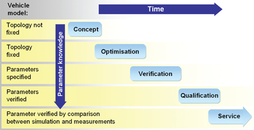

Figure 1: Phases of the railway vehicle engineering process and status of parameter knowledge and vehicle modelling
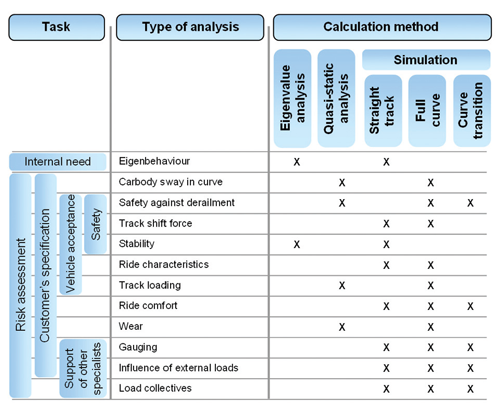

Figure 2: Typical dynamics analyses applied during railway engineering
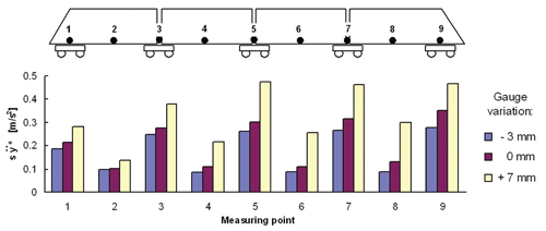

Figure 3: Lateral accelerations (rms values) on the floor of car bodies as a result of simulation at a speed of 160 km/h. Increased gauge leads to very low conicity and hence to a deterioration in ride characteristics
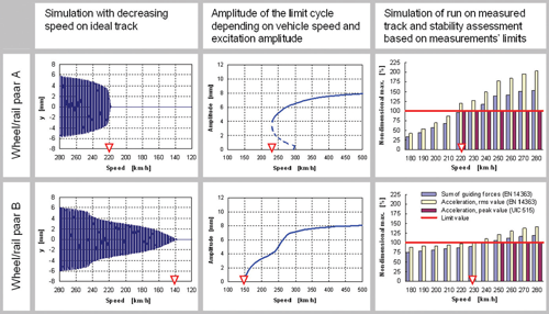

Figure 4: Influence of differing methodologies and wheel/rail contact geometries withthe same equivalent conicity for an amplitude of 3mm on the results of stability assessment
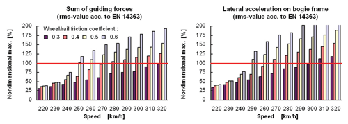

Figure 5: Influence of wheel/rail friction coefficient on the stability assessment according to EN 14363 as a result of simulations on measured track irregularities (presented as non-dimensional values to the limit value)
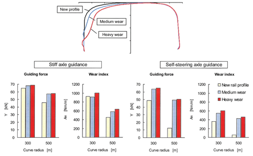

Figure 6: Increase of guiding force and wear index on the outer leading wheel of a four-axle locomotive due to wear on the outer rail. Simulations results for bogie with stiff axle guidance and bogie with self-steering interconnected wheelsets
References
- Wassmer, R., Jakob, J.: Bogies for all applications. Global Railway Review, No. 2/2004, pp. 89-94
- Jakob, J.: FlexCompact – versatile, reliable and durable. Global Railway Review, No. 2/2007, pp. 89-93
- EN 14363: Railway applications — Testing for the acceptance of running characteristics of railway vehicles — Testing of running behaviour and stationary tests, CEN, Brussels, June 2005
- Polach, O.: On nonlinear methods of bogie stability assessment using computer simulations. Proceedings of the Institution of Mechanical Engineers, Part F, Journal of Rail and Rapid Transit, Vol. 220, No. F1/2006, pp. 13-27
- Polach, O.: Comparability of the non-linear and linearized stability assessment during railway vehicle design. Proceedings of the 19th IAVSD Symposium, Milan, Italy, August 29 – September 2, 2005. Vehicle System Dynamics 44 (2006), Supplement, pp. 129-138
- Polach, O.: Bogie design for better dynamic performance. Example of a locomotive bogie. Global Railway Review, No. 1/2003, pp. 69-77
- Himmelstein, G.: The mechatronic bogie – a novel design. Global Railway Review, No. 4/ 2005, pp. 65-68
- Schneider, R., Himmelstein, G.: Active radial steering and stability control with the mechatronic bogie. Proceedings of the 7th World Congress on Railway Research (WCRR 2006), June 4-8, 2006, Montréal, Canada
- Polach, O.: Creep forces in simulations of traction vehicles running on adhesion limit. Wear 258 (2005), pp. 992-1000
- Stichel, S., Mohr, H., Ågren, J. and Enblom, R.: Investigation of the risk for rolling contact fatigue on wheels. Paper on the 20th IAVSD Symposium, Berkeley, California, August 13-17, 2007. To be published in Vehicle System Dynamics
- Enblom, R. Berg, M.: Simulation of railway wheel profile development due to wear – influence of disc braking and contact environment. Wear 258 (2005), pp. 1055-1063


