Development process of a side bumper crash device
Posted: 26 September 2009 | | No comments yet
Voith Turbo Scharfenberg GmbH & Co. KG (SCHAKU) is a world wide known manufacturer of couplers for rail vehicles. Beyond their traditional business, SCHAKU has become an established supplier of complete front end systems. With the introduction of the EN15227, a crash suitable design for the front end of trains has become their focus.
Voith Turbo Scharfenberg GmbH & Co. KG (SCHAKU) is a world wide known manufacturer of couplers for rail vehicles. Beyond their traditional business, SCHAKU has become an established supplier of complete front end systems. With the introduction of the EN15227, a crash suitable design for the front end of trains has become their focus.
Voith Turbo Scharfenberg GmbH & Co. KG (SCHAKU) is a world wide known manufacturer of couplers for rail vehicles. Beyond their traditional business, SCHAKU has become an established supplier of complete front end systems. With the introduction of the EN15227, a crash suitable design for the front end of trains has become their focus.
System solutions of SCHAKU cover the complete front end energy absorption. The Talgo 250 front end (see Figure 1) can absorb more than 1.8MJ in multiple stages within the coupler, respectively by downstream crash elements.
For locomotives and freight cars, SCHAKU has developed an energy absorber which can be mounted between a UIC buffer and a rail vehicle. At a trigger force of approximately 2000kN, the mean force level amounts to 1900kN. When combined with a crashworthy UIC category C buffer, energy absorption of more than 1MJ per buffer system is possible, without intruding into the underframe.
Development of a concept for the energy absorber
Requirements
SCHAKU has been assigned to develop an energy absorber that can be mounted between the locomotive underframe and a category C buffer with the technical properties specified in UIC 526-1. In an ideal situation, the whole system has to absorb the energy of scenario 1 to 3 of EN15227 (see Figure 3).
The standards of UIC526-1, EN12663, and EN15227 include further requirements of the energy absorber to be considered. Installation space and vehicle mass is defined by the customer. At the start of the development, the following three boundary conditions have been determined:
Geometry
- The overall length must not exceed 1,100mm. The position of a separation plane between crash buffer and energy absorber is specified by the UIC buffer length of 620mm
- The flange surface of the car underframe and its hole pattern are specified by the customer
- The standard hole pattern for buffers of UIC526-1 at the separation plane has to permit mounting of different types of UIC buffers
- The system must neither protrude into the locomotive underframe when mounted, nor intrude upon it during a crash
Forces and stationary loads
- The strength of the locomotive underframe restricts the mean deformation force per system to 2000kN. Force peaks higher than this must not last longer than 5ms
- The static testing forces F2 and F3 according to UIC526-1, have to be transferred to the locomotive underframe without permanent plastic deformation. Since the system absorbs the energy in a controlled way at a maximum force of 2000kN, the testing force F1 is irrelevant
- The loads resulting from stationary accelerations according to EN12663 chapter 4.5 are minor compared with UIC testing loads; however, they have to be examined
Energy absorption
- A multi-staged system is required. In accordance with UIC526-1 category C, the first stage is to absorb minimum 70 kJ at a stroke of 105mm in a reversible way
- Due to the given overall length and the maximum admissible force, a second stage of energy absorption has to be integrated into the overall length of the UIC buffer. In less serious accidents, it shall absorb the energy in an irreversible way. A quick replacement of the first two energy absorption elements shall be possible
- The third device is designed to absorb as much energy as possible. Scenario 2 of EN15227 is relevant for dimensioning as the collision partner is only provided with a category A buffer. A target energy absorption of 1MJ per system shall be obtained, so that two systems are able to absorb the whole energy of a 90t vehicle
- At an impact with a vertical offset of 40mm, the function of the system must be guaranteed. The energy absorption can differ, compared to a straight impact
Determination of the design principle
Based on many years of experience in the development of crash elements such as deformation tubes and collapsible crash boxes, several possible designs have been developed and assessed. It was determined that marketed crash buffers were utilised for the first two stages. For the third stage, the decision matrix shown in Table 1, was prepared. It compares the deformation tube and the crash box at given space and a maximum admissible force.
Deformation tubes offer the possibility to adjust the trigger force and the mean force level. The energy absorption is nearly linear. The ratio of overall length and stroke turned out to be irrelevant for the planned overall system.
Finally, a system consisting of a crash-worthy category C buffer and a deformation tube was selected and is shown in Figure 4.
Definition of energy absorption stages
The individual stages of energy absorption must be clearly separated for further dimensioning and subsequent evidence. Speed dependent limits for each stage were defined in consultation with the buffer manufacturer and the customer. Based on scenario 2 of EN15227, the impact of a 90t locomotive to an 80t freight wagon was selected as the dimensioning scenario.
Simulation of the entire system
For the variant ‘Sim-v10′ as shown in Figure 6, a model of the overall model was investigated in detail. Simulations at different velocities with and without vertical offset were carried out.
The dimensioning of the deformation tube could still be done with a quasi static stress-strain-curve. For the investigation of the overall system at different impact velocities, strain rate dependent material parameters are necessary. They were determined at probes in a servo hydraulic test device.
A result of the simulations is that it confirms the advantages of the deformation tube principle. After a relatively low trigger peak, the force stays at a constant high level. The system operates reliably at a vertical offset; the resulting vertical loads are relatively low.
Validation of the entire system
Compared with established deformation tubes, the diameters of the innovative third energy absorption element are extremely large. The reason for this is that the UIC crash buffer must be able to intrude. To validate the influence for the simulation of the overall system, a prototype was tested dynamically at different velocities.
Dynamic validation
Results of dynamic validations
The test with the entire system has been successfully performed. In Figure 6, the force-stroke-curves of the three tests are shown. They state the speed limits between the single energy absorption stages.
The trigger force of the third energy absorption element is approximately 2150kN. The mean force level is approximately 1900kN. In conjunction with the crash buffer, an overall energy absorption of 1,05MJ was reached.
Figure 7 shows photos of the deformations at different collision velocities, taken with a high-speed camera. At lower speed, no permanent deformations occur (Stage 1). At midrange speeds, the irreversible deformation takes place within the crash buffer (Stage 2). At high-speed, the third energy absorption element acts in addition to the other (Stage 3).
Conclusion
The principle of energy absorption by means of deformation tubes once more has excellently adapted in a new area of application.
SCHAKU has gained fundamental knowledge at the design of deformation tubes in coupler shanks. In the meantime at SCHAKU, suchlike energy absorption elements are applied to Pivoting joints for jacobs-bogies or buffer systems. Deformation tubes are marked by the following attributes:
- Constant high mean force level; optimal energy absorption
- Low trigger forces
- Excellent adjustability
- Predictable function even under eccentric load
These properties of deformation tubes will lead to an increased usage within the area of irreversible energy absorption. SCHAKU will develop additional applications for deformation tubes. In combination with existing systems, SCHAKU can offer tailor made crash concepts to customers.
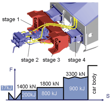

Figure 1: Multi-level crash concept at Talgo 250
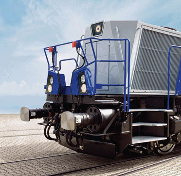

Figure 2: Energy absorber at Gravita Locomotive
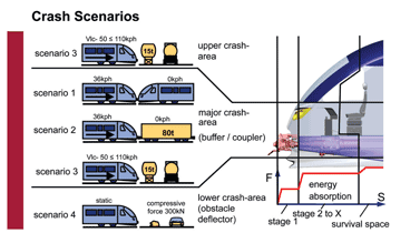

Figure 3: Requirements from EN15227
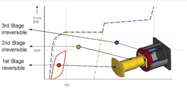

Figure 4: Concept Energy Absorber
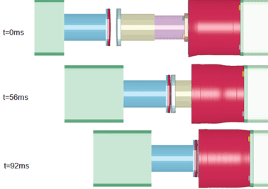

Figure 5: Simulation deformation tube entire system
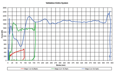

Figure 6: Results dynamic test
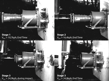

Figure 7: Deformation behaviour at different collision velocities
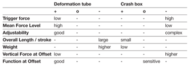

Table 1: Decision matrix
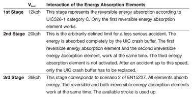

Table 2: Definition of the energy absorption phases


