

Design of prestressed concrete sleepers
Posted: 28 July 2006 | | 5 comments
The basis for design work for prestressed-concrete sleepers in Europe is EN 13230, valid since October 2002: “Concrete sleepers and bearers.” A supplement to this standard is UIC 713: “Design of Monoblock Concrete Sleepers,” which provides a design example for a prestressed-concrete sleeper. The design bending moment calculated here accounts for the dynamic live loads for a track-system with a lifetime of 40 years. The sleeper must be capable of assuming this design moment without cracking.
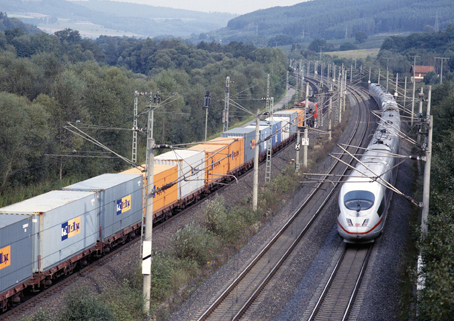
Figure 1: Ballasted track systems for high demands
In the USA, design of prestressed-concrete sleepers is based on Chapter 30, Part 4 of the AREMA specification “Concrete Ties”, in the version dated 2003. Here as well, the specification calculates a design moment that the sleeper must assume without cracking. The difference between AREMA and EN 13230 consists in calculation of the design moments, for which more rigorous requirements are specified by AREMA, especially with regard to the rail seat.
The present study describes the salient differences between the two standards – by application of the Cooper E80 freight-train load (used as standard in the USA, (see Fig. 1), with a converted maximum axle load of 347 kN – and explains the consequently resulting deviations in requirements placed on the sleepers. The result of this comparative design project was the creation of a new sleeper that satisfies the requirements for extremely heavy-haul axle loads: in conformity with both AREMA as well as EN 13230.
Design wheel load on concrete sleepers
The design wheel load, also known as dynamic support-point force, is the force that acts on the sleeper and that, in turn, produces the design moment. In bending tests, the concrete sleeper must be able to withstand this design moment without the formation of cracks. The design load is calculated from the static wheel load Q of the train, which makes up 50% of the axle load: i.e., 173.5 kN.
This force is furthermore influenced by the dynamic factor γv, which takes the speed and faults in vehicle geometry into consideration: e.g., wheel flats. With respect to the dynamic factor, EN 13230 distinguishes only between speeds up to 200km/h, and speeds greater than 200km/h. For design purposes, assumption is made of a maximum speed of 160km/h. Under these conditions, γv = 0.5; for v > 200 km/h, γv would equal 0.75. It is, furthermore, possible to take into account the damping effect γp of the rail-fastening system. Employment of an elastic rail pad attenuates dynamic effects and enhances distribution of the applied load onto several sleepers as a result of rail deflection. This, in effect, reduces the loads applied to each of the individual sleepers. Since elastic rail pads are not used for standard ballasted tracks, low attenuation of γp = 1.0 is applied in calculations for such tracks, to provide an additional margin of safety. For medium damping levels, the factor is approx. 0.89; for high damping, around 0.78. These two values are used to calculate the combined dynamic factor as follows:
![]()
Partial safety coefficients, furthermore, are also taken into account here. The first such factor is γr = 1.35 for flaws in track substructure: e.g., asymmetric support (cavities in the ballast) under the sleepers. The second such factor is γi = 1.6 for faults in track positioning: for example, irregular placement of the sleepers. This results in a total safety coefficient of 2.16. An additional essential aspect is the load-distribution effects of the rail. For sleeper pitch (i.e., interval between the sleepers) up to 650mm, and for a rail with a mass greater than 46 kg/m, a factor of γd = 0.5 is applied: i.e., 50% of the wheel load acts directly on the sleeper located immediately beneath the wheel, with 25% acting on each of the two adjacent sleepers. Consideration of all these factors results in a total dynamic coefficient of von γTot = 1.5 · 2.16 = 3.24 to be applied to the static wheel load. This enables calculation of the design load, in accordance with EN 13230, as follows:
![]()
The dynamic and load-distribution factors are also calculated for the design wheel load in work carried out in accordance with AREMA. Unlike work performed in accordance with EN 13230, however, calculations on the basis of AREMA do not apply a general assumption of 50% for load-distribution effects: instead, the percent employed is selected as a function of the sleeper pitch (interval) (Fig. 2).
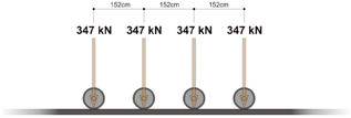
Figure 2: Load configuration for Cooper E 80
For typical sleeper-pitch values of 600 to 650mm, the load distribution factor will lie between 49 and 53%. With the factor of 50% as used with EN 13230, therefore, calculations on the basis of this standard are based on a sleeper pitch of 610mm. In work with AREMA, greater values result in conjunction with larger sleeper intervals: i.e., the load-distribution factor and, in turn, the sleeper load, become larger.
AREMA does not enable exact calculations with account taken of the rail or the ballast reaction. This, however, is possible by application of the Winkler-Zimmermann method, in accordance with the theory of an elastically supported beam. For the further calculations to be performed in the present study, a sleeper pitch of 610mm will be employed, in order to obtain a load-distribution factor of 0.5 for both standards.
For the dynamic wheel load in accordance with AREMA, a general factor of 200% is applied to the static wheel load. This influencing factor (IF) arises as a result of the dynamic effects of the wheel and of the rail and/or track faults. Accordingly, the design wheel load is calculated as follows:
![]()

Figure 3: Load distribution on the basis of AREMA, Section 4.1.2.3
Although this result for the design wheel load is less than that calculated with EN 13230, an additional factor comes into play with AREMA. This represents the greatest difference in the influencing variables, since the annual tonnage is considered here, and the speed is exactly taken into account (Fig. 3). Whereas EN 13230 draws distinctions only above and below the speed of 200km/h, AREMA calculations exactly determine the speed factor.
A factor of V = 1.1 results on the basis of a speed of 160km/h. AREMA, furthermore, determines an influencing factor as a function of the annual tonnage: a factor not taken into account by EN 13230. For annual tonnage of 75 million metric tonnes, the tonnage factor would also be T = 1.1. This results in a total factor, for speed and tonnage, of V+T = 1.21.
Work with AREMA therefore leads to a total factor of 3.6 to be applied to the static wheel load, in comparison to 3.24 obtained with EN 13230. The design wheel load is accordingly greater: 315 kN instead of 280 kN. The further calculations are based on this greater wheel load, in order to achieve comparable results in moment calculations.
Calculating the design moments on sleepers
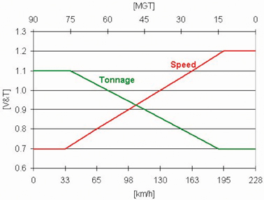
Figure 4: Tonnage and speed factors in accordance with AREMA, Section 4.4.1.2
The design wheel load as determined above is now used to calculate the design moments. EN 13230 takes into account two loading cases of primary importance. The first case involves freshly tamped sleepers. In this case, ballast compaction takes place only in the area of the rail seat (Fig. 4). The length of ballast compaction is equal on both sides of the rail. For this loading case, the greatest positive moment occurs at the lower side of the sleeper.
In calculations of the design moment under the rail, EN 13230 stipulates a rounded transition between moment curves: i.e., the application of loads takes place over the rail seat, and not at a single point. EN 13230 further specifies here that the force applied be attenuated under an angle of 45°, up to a point at approximately half the sleeper height (Fig. 5). In this way, the width of the rail seat and the sleeper height will influence the moment, since the introduction of loads is changed as a function of rail-base width and sleeper height. The length of the sleeper likewise has an effect, since the projecting end of the sleeper Lp will change, thereby modifying the length of the lever arm. The sleeper length can be shortened to reduce the moment. This, however, has the result that the moment will increase at the centre of the sleeper. This effect is then taken into consideration in the second loading case of primary importance. For loading case no. 1, the positive design moment is calculated as follows:
![]()
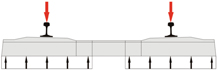
Figure 5: Load case no.1
AREMA does not take this application of loads into consideration. The plot of moments shown in Fig. 6 makes clear this major difference between the two standards. This plot was calculated for a sleeper 2.6m long, with a design wheel load of 315 kN. These calculations were further based on a UIC 60 rail, with rail seat 150mm wide and a sleeper height of 233 mm under the rail. A value of 43.3 kNm results without rounded transition between moment curves (shown in Fig. 6 as “without reduction”); with the rounded transition, the value is 28.6 kNm (shown in Fig. 6 as “with reduction”). This is approximately equivalent to a reduction of 34%.
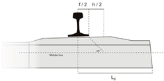
Figure 6: Positive design bending moment according to EN 13230
The AREMA specification does not give formulas for calculations of the moments. Instead, it provides a graph for the design moments with various sleeper lengths and sleeper pitches (Fig. 7). The tonnage and speed factor V+T has not yet been applied to these values, however: i.e., the moments are provided for a design wheel load of 260 kN, and must later be multiplied by the V+T factor of 1.21. For a sleeper length of 2.6 m and a sleeper pitch of 610 mm, this diagram shows an unfactored positive bending moment of approx. 34.3 kNm. Application of the tonnage and speed factor V+T yields a result of 41.5 kNm.
This procedure results in approximately the same moment as with calculations in accordance with EN 13230 and without rounded transition between moment curves. This reveals that the two calculation methods yield approximately the same values for the positive design moment under the rail seat. Work with EN 13230, however, involves an additional reduction as a result of the application of forces, which means that requirements decrease by approx. 31%: i.e., from 41.5 kNm (according to AREMA) to 28.6 kNm (in accordance with EN 13230).
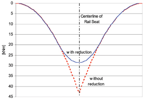
Figure 7: Plot of positive bending moment at rail seat
In the second load case, uniform ballast compaction takes place under the entire sleeper. This condition arises after relatively long track operational time, after the dynamic processes of passing trains acting on the system distribute and compact the ballast under the sleeper (Fig. 8). Under these conditions, the sleeper begins to “ride”, and the largest negative moment occurs at the upper side, in the middle of the sleeper. The sleeper bedding area and the length of the sleeper play a major role here. A waist at the middle of the sleeper offers the advantage (Fig. 9) of a reduction in load and in moment. The following equations allow calculation of the negative moment, in accordance with EN 13230, for sleepers with and without waists:
Without waist:
![]()
With waist:


Figure 8: Unfactored positive bending moments at rail seat, AREMA Section 4.4.1.1
The AREMA specification contains a graph for calculation of the negative moment at the middle of the sleeper (Fig. 10). This diagram shows the negative moment to be a function of the sleeper length and of the positive moment. These values are based on a sleeper with a uniform width: i.e., a sleeper without a waist. For a length of 2.6m, for example, the negative moment at the middle of the sleeper is 65% of the positive moment at the rail seat. In other words, with the value of 41.5 kNm calculated above for the positive moment at the rail seat, a negative moment of approx. 27.0 kNm will occur, according to AREMA, in the middle of the sleeper. On the basis of AREMA, a waist in the middle of the sleeper can be expected to result in a reduction of approx. 10%. If the moment is calculated for the exact sleeper bedding area for load case no. 2, in accordance with EN 13230, and with a design wheel load of 315 kN, a moment of 31.5 kNm results for a sleeper without a waist. This signifies that the values specified in EN 13230 are approx. 17% greater here than those contained in AREMA. For a sleeper with a waist, the moment decreases to 24.7 kNm: i.e., a reduction of the AREMA moment by 10%. The following conclusion is therefore justified here: for sleepers with uniform width, the specified values for the sleeper middle as set forth in EN 13230 are approx. 17% greater than the requirements in accordance with AREMA – whereas the two standards provide approximately the same results for work with sleepers with waists.

Figure 9: Load case no.2
As stated in conjunction with the calculation of the positive moment in the rail fastening, the plots of the curves here clearly reveal that a reduction in sleeper length causes a pronounced increase in the negative moment at the middle of the sleeper. This consequently signifies that the selection of sleeper length plays an essential role in achieving harmony in the two standards. A long sleeper produces a large positive moment at the rail fastening; with a short sleeper, in contrast, the requirement placed on the negative moment at the sleeper middle becomes more rigorous. Harmony is achieved here for sleeper lengths of 2.5 to 2.7m.
This diagram additionally provides the data for the negative moment in the rail fastening, and for the positive moment at the middle of the sleeper. EN 13230 does not require testing for these values, or it classifies such testing as optional. The present study will therefore not further consider these two moments.

Figure 10: Sleeper with waist
In order to satisfy both the stringent specifications set down by AREMA, as well as those by EN 13230, a new sleeper has been developed: the UP 04 (see Fig. 11), which conforms to the respective maximum requirements in both standards. The table below once again recapitulates the various specifications for an axle load of 347 kN. This table takes into account the various calculation techniques contained in the two standards: for design wheel load and for the design moments. The first column shows the specifications as set down in AREMA, with a constant width of the sleepers, and without rounded transition between moment curves. The next two columns give the design moments according to EN 13230: each with and without rounded transition between moment curves (“moment reduction”) under the rail fastening, and with and without a waist at the middle of the sleeper (“reduced centre”) – but with the design wheel load as per AREMA. The fourth column, in contrast, shows the requirements placed for 347 kN axle load, which have been entirely calculated in conformity with EN 13230: i.e., with less design wheel load. The fifth column provides the results of calculations for an axle load of 440 kN, in accordance with EN 13230. The fifth column details results for the actual moment causing cracking for the UP 04, as determined in testing at Munich Technical University. This data unquestionably demonstrates that this new sleeper performs appreciably better than the requirements placed by AREMA. It is furthermore evident that the requirements for axle load of 440 kN are likewise fulfilled. Official certification tests were also conducted in accordance with EN 13230 for this axle load at Munich Technical University: tests which were successfully passed.
Railway sleeper tests

Figure 11: Calculation of bending moments, in accordance with AREMA, Section 4.4.1.2
Further differences between AREMA and EN 13230 arise in conjunction with official certification testing. Bending tests in accordance with AREMA, for example, are performed on only one sleeper. Here, positive and negative bending tests are first conducted at both rail fastenings, and in the middle of the sleeper: i.e., for a total of six static bending tests.
The stipulations for AREMA static bending tests require application of the design moment without the appearance of cracks in the sleeper. This procedure represents the entire sequence for the static bending test; this test comes to an end at this point. Certification testing as per AREMA next involves fatigue testing for one rail fastening: by application of loads until the sleeper cracks up to the first prestressing tendon. Three million loading cycles are subsequently applied to the sleeper, whereby the peak load applied in each load cycle amounts to 10% more than the design moment. The sleeper passes the test if, after three million loading cycles, it can withstand, without breaking, a moment that is 10% greater than the design moment. The last AREMA test is an ultimate-strength test performed on the other rail fastening, whereby the breaking moment is stipulated at only 50% above the design moment. All these specifications signify that a sleeper must undergo a total of eight bending tests.
For testing in accordance with EN 13230, the stipulations for testing differ radically from those in AREMA, with regard to the number of test sleepers alone. EN 13230 calls for the testing of no fewer than a total of 16 sleepers: whereby only one test may be performed on each sleeper. Static bending tests are performed on six rail fastenings for positive moment, and on the centres of three sleepers for negative moment.

Figure 12: The new UP 04 sleeper for heavy-haul lines, designed in accordance with both AREMA and EN 13230
In this testing, the sleeper is loaded with the design moment, and must not crack here as well. Unlike AREMA, the cracking moment according to EN 13230 is determined for each sleeper. Furthermore, EN 13230 stipulates the moment for the rail fastening for which the crack must re-close to such an extent that the crack width is less than 0.05mm upon removal of the test load. In addition, this standard specifies the breaking moment at the rail fastening for the six sleepers. The design moment must be multiplied by the k values for determination of these moments. EN 13230 establishes these k values, for example, as 1.8 for the 0.05 mm cracking moment in a non-loaded state, and 2.5 for the breaking moment. This evidences that the testing specifications are appreciably more demanding in EN 13230 than in AREMA: in comparison, for example, the breaking moment for AREMA is 1.5 times the design moment, and for EN 13230, it is 2.5 times the design moment.
In addition to the static tests, EN 13230 requires 6 further dynamic tests performed at the rail fastening. In the EN 13230 dynamic testing (not stipulated by AREMA), the procedure is carried out analogue to that for static testing: i.e., here as well, the cracking moment, the 0.05 mm crack-width moment for a condition without loading, and the breaking moment all must be determined – to be sure, with lesser k values (1.5 and 2.2). The final required test is an ultimate-strength test, for which loading is likewise applied until cracking appears. Subsequently, the sleepers are subjected to two million load cycles, with loading for each sleeper up to the design moment. EN 13230, however, sets the stipulations that the crack under load must be smaller than 0.1mm, and less than 0.05-mm without loading. This standard also determines the breaking moment for the following ultimate-strength test.
Summary
The stipulations set in the USA for sleepers at the rail seat are appreciably more demanding than those in Europe. This results not only from the very high axle load of 347 kN. For design work with this axle load performed in accordance with EN 13230, the design moments are still approx. 31% lower than the requirements stipulated by AREMA. This value is the consequence of the lack of rounded transition between moment curves under the rail fastening. At the same time, however, the requirements placed for the centre of the sleeper are approx. 17% less in the USA than in Europe. These circumstances have practical consequences: in the USA, for example, problems primarily appear at the centre of the sleeper in prestressed-concrete sleepers. In order to satisfy the stipulations contained in AREMA as well as in EN 13230, a new sleeper was designed: the UP 04. For design work in accordance with AREMA, this new sleeper conforms to the requirements for an axle load of 347 kN. In work on the basis of EN 13230, the permissible axle load can be increased to 440 kN. Tests have already been conducted at the Munich Technical University for these high axle loads, which resulted in successful passing of tests for axle loads of 440 kN as stipulated by EN 13230.


What is the diameter of steel wire or strand used for manufacture of prestressed concrete sleepers
Should the bending moments obtained be used for stress check theoretically for tension at service stage?
Can you please send me the table that you mentioned in design moment part?
[email protected]
I need your advice please;
In sleeper design we calculate Positive rail seat bending moment first;
Mr = 12.6kNm
Based on the BSEN table 3 reference test load for pre-production test = 12.6×8= 100.8kN
If the design life is 50 years; Mr will be same throughout its design life = 12.6kNm
Does it mean the sleepers are expected to meet 100.8kN requirement even after 50 years.
Why the reference load doesn’t take into account 50years of time dependent losses of prestressing force normally 20% reduction.
Very interesting article. The differences between the two specifications have been brought out and explained very clearly. Thanks to the authors.