Shape optimisation of a railway wheel profile
Posted: 3 April 2006 | | No comments yet
Delft University of Technology has developed and successfully implemented a procedure for optimisation of a railway wheel profile. An optimised wheel profile reduces wheel/rail wear and prevents vehicle instability.
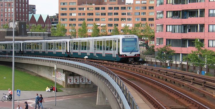
Figure 1: RET metro, Rotterdam, The Netherlands. Courtesy of www.retmetro.nl
During the last decades substantial progress has been made in the design of railway vehicles and running gear. Tilting trains, high speed trains, active steering wheelsets and other sophisticated solutions have been introduced. In spite of this progress, the mechanics of a railway wheelset remains unchanged and an inappropriate combination of wheel and rail profiles can easily undermine these technological advances. Besides, older equipment has a special need for appropriate combinations of wheel/rail profiles as they do not have high-tech devices that improve their performance.
The design of a wheel profile is an old problem and various approaches were developed to obtain a satisfactory combination of wheel and rail profiles. Usually, it is possible to find an optimal combination when dealing with a closed railway system, i.e. when only one type of rolling stock is running on a track and no influence of other types of railway vehicles is present. Examples of such systems are heavy haul and tram lines. In the present paper such closed system is considered, namely the Rotterdam metro network (RET) in The Netherlands (Figure 1).
The kinematical properties of wheel and rail contact, such as rolling radius, contact angles and wheelset roll angle vary as the wheelset moves laterally relative to the rails. The nature of the functional dependence between these geometrically constrained variables and the wheelset lateral position is defined by the cross-sectional shape of wheel and rail. By studying the geometrical characteristics of the contact between wheel and rail it is possible to judge the dynamic behaviour of the wheelset and dynamic properties (such as stability) of the vehicle.
The wheel and rail cross-sectional shapes define not only the kinematical and dynamical properties of the wheelset, but also the physical properties such as contact stresses, creep and wear. Therefore, an ill-designed combination of wheel and rail profiles can be a source of various railway problems such as high wear rate of the wheels, instability (hunting) of a wheelset as well as rolling contact fatigue defects of the rails. These problems on their turn lead to cost inefficiency and are unsafe when exploited.
Typically, a wheel profile was designed using a trial and error approach, based on a designer’s intuition and experience as well as the use of measurement data. During the last decades efforts have been made to use numerical methods in the wheel design process. In this article a procedure (described in Figures 6 and 7) is applied to improve the performance of metro vehicles that were suffering from severe wheel wear and instability.
Wheel/rail contact properties
An important characteristic of the contact between wheel and rail is the rolling radius of a wheel at the contact point 2, 3. This radius can be different for the right and left wheel as a wheelset is moving along a track (r1 and r2 respectively, as shown in Figure 2).
, corresponding to wheelset displacement y, the wheels are conical, y is the conicity of the wheels")
Figure 2: Rolling radius (r1 and r2), corresponding to wheelset displacement y, the wheels are conical, y is the conicity of the wheels
When a wheelset is in a central position with respect to the track the rolling radius of the left and right wheel are the same, namely r1 = r2 = r. An instantaneous difference between the rolling radius of the right and left wheel can be defined as a function of the lateral displacement y of a wheelset with respect to its central position (Figure 2), according to the formula:

The rolling radius difference (RRD) is one of the main characteristics of wheel/rail contact that defines the behaviour of a wheelset on a track. For example, to pass a sharp curved track without slippage between wheels and rails, an appropriate RRD of the wheelset is required. Avoiding the slippage is important from the wheel and rail wear point of view.
Generally, the rolling radius difference is a non-linear function of the lateral displacement y of a wheelset, which, from geometrical considerations (Figure 2), can be written as:

where g is the wheel conicity. The effective or equivalent conicity γe is determined at a certain lateral displacement y = y. It should be noted that for a purely conical wheel the equivalent conicity is equal to the cone angle of the wheel, i.e. γe = γ.
Examples of rolling radius difference functions (also known as a ‘y – Δr’ curve) for purely conical and worn profiles, are given in Figure 3. Due to wear a wheel profile changes (Figure 4) and consequently its RRD function.

Figure 3: Rolling radius difference functions
A linear conical wheel profile widely used in the past has bi-linear characteristics of the rolling radius difference, as shown in Figure 3. This results in shocks when the wheel flange and rail come into contact during the wheelset motion. A worn wheel better matches a rail and therefore has a smoother RRD function. However, high conicity of a worn wheel reduces the critical speed of a wheelset and results in severe vehicle oscillations (hunting). Obviously, an optimum profile is a compromise between stability and wear. Traditionally, such a compromise is achieved by manually modifying the wheel shape to find satisfactory contact characteristics in combination with given rail. An optimum wheel profile should satisfy the following:
- Low wheel wear rate
- Wheelset stability
- Acceptable contact stresses
However, this design approach is quite time consuming and expensive.
The use of numerical simulations and optimisation methods looks more efficient. The approach discussed in this paper concentrates on finding a wheel profile satisfying an optimised y – Dr curve. When the optimum rolling radius difference function Dr(y) for a given rail profile is known, one can try to solve an inverse problem in order to find a wheel profile with such an RRD. This approach is formulated as an optimisation problem.

Figure 4: Worn and unworn wheels
Wheel design procedure
The wheel profile design procedure is shown schematically in Figure 5. The first step is an analysis of the current wheel/rail profiles. Profile measurements with, for instance, the MiniProf system are used to analyse the wheelset contact properties to design a target RRD function. The second step is the definition of an optimum (target) RRD function. The problem of finding a wheel profile corresponding to the target RRD function was formulated as an optimisation problem. The problem has been solved using the MARS optimisation method, which was successfully used for various real-life applications 5. Since the dynamic properties of a vehicle are not directly controlled during the optimisation process, which in fact reduces the computational efforts of the optimisation, they must be verified afterwards. The optimised profile is tested for stability, wear and dynamic contact stresses with the ADAMS/Rail computer package1. If the dynamic performance of a vehicle with the obtained wheel profile does not satisfy the imposed requirements, the RRD function should be adjusted and the optimisation should be performed again in an iterative process.

Figure 5: Flowchart of wheel profile design procedure
Design variables
To describe the geometry of a wheel profile, a number of points on its flange, flange root and tread are chosen. Connected by a piecewise cubic Hermite interpolating polynom, these points define the shape of the wheel profile, as shown in Figure 6. The positions of these points can be varied in order to modify the profile. For tangent track only the points ambient to the wheel tread are considered. In this case, stability is the dominant factor. In curves points ambient to the flange root and the filed side are selected. Here wear and contact stresses are dominant.

Figure 6: Wheel profile, moving and constrained points
Objective function and constraints
Since the optimum wheel profile is defined by the target RRD the difference between the resulting RRD and the target RRD should be as small as possible. The target RRD function is divided on three parts which are responsible for tangent track, curved track and sharp curves. For tangent track conicity at y = 0 should be maintained in the range 0.025-0.2 for TGV trains and metro trains respectively, to provide a sufficiently high critical speed of a vehicle. On a curved track with a large radius the corresponding rolling radius difference must allow the wheelset to find the radial position in a curve to prevent wheel creepage. In sharp curves wheels are expected heavy flange contact. In this case the RRD must be as high as possible. The complete procedure of selection of the target RRD function is described by Shevtsov, I.Y., Markine, V.L. and Esveld, C.7.
Two safety requirements are included, i.e. wheel flange thickness and minimum flange angle to prevent vehicle derailment.
Dynamic analysis
The vehicle is modelled using ADAMS/Rail 1. The dynamic simulations are performed on specially designed tracks. On straight track the wheel profile is tested for vehicle stability and wear. On curved track the wheel profile is tested for curving behaviour, wear and RCF.
Wheel wear is estimated using the wear index calculated according to the formula4:

where F1 is the longitudinal creep force; x is the longitudinal creepage; F2 is the lateral creep force and h is the lateral creepage.
Wheel profile design for RET metro
History
The wheel profile design procedure described in the previous section has been applied to improve the performance of some RET metro trains. In 1999 the existing NP46 rails were replaced by S49 rails. The profiles looked similar and therefore no difference in the train performance was expected. However, after the introduction of the new rail profile the metro trains started to experience severe lateral vibrations. At the same time a high level of wheel wear was observed after a relatively small mileage. In fact, these vibrations were caused by the worn wheels. Immediately after these vibrations had been observed the wheels were re-profiled to prevent derailment. Thus, due to the replacement of the rails the lifetime of the wheels was reduced from 120,000 km (with the rails NP46) to 25,000 km (with the rails S49). The Railway Engineering Group of TU Delft was commissioned a research work to improve vehicle stability and wheel life.
Analysis of the problem
The problem has been solved in several steps. Firstly, a comparison of the old and new rails has been performed. It should be noted that the S49 rail is installed with an inclination of 1:40 whereas NP46 rail is installed as normal. Even though the rail profiles NP46 and S49 look similar (Figure 7a) there is a small difference between these two profiles which only becomes visible while zooming in the top of the rails, as shown in Figure 7b. However, such small differences, in the order of tenths of a millimetre, are responsible for substantial changes in vehicle behaviour.
")
Figure 7: Comparison of rails NP46 and S49 (a. not zoomed; b. zoomed in)
In the next step the wheel/rail contact characteristics of the old and new situation have been investigated. The wheel/rail contact points for new (unworn) wheel profile UIC510 with the unworn NP46 and S49 rails respectively, are shown in Figure 8. In this figure the lines between the wheel and rail profiles connect the corresponding contact points, which were calculated per 0.5 mm of the lateral wheelset displacement. The lateral wheelset displacements are shown above the wheel profile. The coordinate system in this figure is the wheelset coordinate system ywOzw (Figure 2) with the origin in the centre of the wheelset in neutral position. It should be noted that in this figure the wheel is shifted 10 mm vertically.
 and rails - NP46 (a) and S49 (b)")
Figure 8: Contact points of unworn wheel (UIC510) and rails – NP46 (a) and S49 (b)
By comparing Figure 8a and Figure 8b one can observe a discontinuity (a big jump) in the position of the contact point on the S49 rail around the neutral wheelset position. Since the displacements in the range +/- 2 mm typically correspond to the motion of a wheelset on a straight track, many such jumps will occur during the vehicle motion. Due to these contact point jumps the wheel profile wears very rapidly. This ultimately results in very large jumps of the contact point as shown in Figure 9. This figure shows the contact points of a worn (measured) UIC510 wheel profile and a S49 rail. These large jumps of the contact point were also the source of the vibrations observed in the metro trains. On the other hand the wheel/rail combination UIC510-NP46 has more uniformly distributed contact points on a straight track (corresponding to wheelset displacements of +/- 2 mm), as shown in Figure 8a. As a result, the wear rate of the UIC510 wheels on the NP46 rails was much lower and therefore the wheel lifetime was relatively long (120,000 km).
 UIC510 wheel and S49 rail")
Figure 9: Contact points of worn (measured) UIC510 wheel and S49 rail
As was mentioned earlier, the rolling radius difference plays an important role in the vehicle dynamics and has therefore been investigated next. The RRD functions for the UIC510 wheel profile on the NP46 and S49 rails, respectively, are shown in Figure 10. This figure reveals that the UIC510/S49 wheel/rail combination has a much higher inclination compared to the UIC510/NP46 combination. This also means that the corresponding equivalent conicity2 is higher for S49 than for NP46. The high conicity was the reason for large vehicle vibrations, high tread wear and ultimately the relatively short lifetime of wheels.
Design of a wheel profile
After the source of the vehicle instability problem was found, the next step was to improve (optimise) the wheel profile. The UIC510/NP46 wheel/rail combination (Figure 10) has a conicity of 0.2. The metro vehicle on wheels with such conicity is stable. Therefore, the UIC510/NP46 RRD function has been chosen as the target RRD function in the optimum wheel profile design procedure described earlier.

Figure 10: RRD function: UIC510 wheel on NP46 rail; UIC510 wheel on S49 rail, optimised wheel on S49 rail
The shape of the optimum wheel profile is shown in Figure 11. Even though the changes in the shape are not significant, they result in quite substantial changes of the RRD function as shown in Figure 10. The RRD function of optimised profile on S49 rail is very close to the target RRD, which means good results of optimisation. The wheel/rail contact points are shown in Figure 12. It can be observed that the contact points are very well distributed in the range from -4 mm to 4 mm of the lateral wheelset displacement. Such contact will result in much lower wheel wear.

Figure 11: Initial and optimised wheel profiles
Dynamic simulations have been performed in order to analyse vehicle stability and wheel wear. As a result of the optimisation, the critical velocity of a metro train has been increased from 50 m/s for unworn UIC510 to 60 m/s for the optimised wheel profile. The critical velocity for the worn UIC510 profile was 30 m/s, which explained the observed stability problems.

Figure 12: Contact points of optimised wheel profile and S49 rail
The wear indexes of a wheelset with the optimised and UIC510 wheel profiles are shown in Figure 14. From this figure it can be seen that the wear index for the unworn UIC510/S49 wheel/rail combination is significantly higher than for the optimised wheel profile (lower wear). The explanation can be found in Figure 15. The optimised wheel on the S49 rail has always single-point contact, while the unworn UIC510/S49 wheel/rail combination always remain in double-point contact, causing high wear rates. This means the optimised profile prevents double point contact and thus reduces wheel wear.

Figure 13: Lateral displacements of wheelset with optimised and UIC510 wheels on S49 rail, velocity 20 m/s
High wheel tread wear leads to a hollow worn profile, causing vehicle instability due to high or negative conicity. This is prevented with the optimised wheel profile.

Figure 14: Wear index of the left front wheel. Optimised and UIC510 wheel profiles on S49 rail
 on the left front wheel. Optimised (single-point contact) and UIC510 wheel (double-point contact) wheel profiles on S49 rail")
Figure 15: Position of contact point(s) on the left front wheel. Optimised (single-point contact) and UIC510 wheel (double-point contact) wheel profiles on S49 rail
Conclusions
In this article a numerical method for wheel profile design was discussed, based on optimisation of the Rolling Radius Difference function.
Using this procedure the wheel profile design for the RET metro trains has been improved. The results of the dynamical simulations have shown that the performance of railway vehicles is improved by improving the contact properties of wheel and rail.
Double point contact between wheel and rail produces high wear and leads to hollow wear of wheels.
The new wheel profile was implemented on the RET metro trains. As a result of this, the instability of the metro trains was eliminated and the lifetime of the wheels was increased from 25,000 km to 114,000 km as of January 2006.
TU Delft will focus future research work on optimisation of wheel profile in order to reduce RCF problems in wheel/rail contact.
Acknowledgements
The authors would like to thank RET for providing measurement data of wheel and rail profiles and metro vehicle data.
References
- ADAMS/Rail (2005) MSC.Software Corporation MSC.ADAMS®, http://www.mscsoftware.com
- Dukkipati, R.V. (2000) Vehicle Dynamics, Boca Raton: CRC Press, ISBN 0-8493-0976-X.
- Esveld, C. (2001) Modern Railway Track, (Second Edition), Zaltbommel: MRT-Productions, ISBN 90-8004-324-3-3. (www.esveld.com)
- Kalker, J.J. (1990) Three-Dimensional Elastic Bodies in Rolling Contact, Dordrecht: Kluwer Academic Publishers, ISBN 0-7923-0712-7.
- Markine, V.L. (1999) Optimization of the Dynamic Behaviour of Mechanical Systems, PhD Thesis, TU Delft: Shaker Publishing BV, ISBN 90-423-0069-8.
- Shevtsov, I.Y., Markine, V.L. & Esveld, C. (2002) One procedure for optimal design of wheel profile, Proceedings of the IQPC conference on Achieving Best Practice in Wheel/Rail Interface Management, Amsterdam, The Netherlands, January 31 – February 1, 2002.
- Shevtsov, I.Y., Markine, V.L., Esveld, C. (2005) Optimal design of wheel profile for railway vehicles. Wear, Volume 258, Issues 7-8, 2005, pp. 1022–1030. ISSN 0043-1648